This link contains building instructions for the DIY vibrotactile PD glove design shown in the diagram. It uses Kris Wilk's LRA-based electronics design.
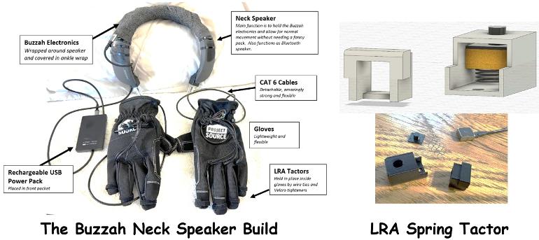
1. The gloves feature a new spring-based LRA tactor design that provides more energetic and focused vibrations than comparable foam-based LRA tactors. When foam is used to decouple LRA tactors, significant energy is lost due to internal friction in the foam. No energy is lost when using springs for this function since springs are almost perfectly elastic.
2. The electronics for the gloves are housed on a Bluetooth neck speaker. This keeps the wires out of the way compared to fanny pack versions. The Bluetooth neck speaker can also sync with your smartphone as a speakerphone and mp3 player.
Written by
TactileDesign
To view profiles and participate in discussions please or .
Hi Mark - I am gearing up to build a set of gloves using your design. However, I can't find files for printing the tactor housing parts or the electronics platform boards. I've searched github with no luck. Please help. 🙂 Thanks.
Hello Wildsidephotog - Sorry about that - I have been tweaking parameters a bit - I will post them on the github site for you by end of the day today! Let me know if you have any other issues - I have tried to be comprehensive in my directions, but there are always things that come up. I check Health Unlocked every day.
That's awesome, Mark! Thanks so much. Your directions are outstanding and very much appreciated. If you're interested, I'll let you know how the build goes.
Hi Mark - I printed a full set of tactor housing parts and have run into some problems. What material do you use to print the parts? I used PLA. What did you set the resolution to when setting up the print job? The problems I've run into are that the button does not fit inside the main housing without significant friction. The other problem is that the end-cap piece is very difficult to insert into the pain housing and actually requires a hammer to get it to seat. Any ideas on what I can do differently?
I just saw your post and will work with you to resolve ASAP. The tightness of the case fit is probably because you used PLA instead of ABS like I did - I remember when I was using PLA in early versions I needed to leave a bit of tolerance so it would not be too tight. PLA will still work, I just need to go back and look at what my tolerance was when I was using PLA. I will check into this and the button fit today and get back to you.
Do you have your own printer you are printing on? If so, what printer are you using? I have a Bambu PS1. Also - do you have any PLA filament to try?
Hi Mark, I'm using a community printer at the library. I don't know the model but it's an Anycubic brand. The first print job I did was with a printer at Hedron Hackerspace here in Portland. I think the resolution was set at .2mm and the density was set too low. I'm working on another try with my local library printer using PLA. The density is set at 80 and resolution is .06 on this run. It's supposed to take nearly 7 hours to complete the print job. Since I'm lined up in a cue, it'll take till Thursday this week before I know more.
I think the hole size and the button size should work but it I need to take another run at it later, I think reducing the button diameter a smidge might work best.
I checked the file I posted and the dimensions were the ones that worked on my printer when using ABS filament. Lets work on your endcap fit first because getting that fit with your printer might take a bit of trial and error... The button will easy to fix because you dont need to get a perfect fit.
My design uses a friction fit for the cap. For my Bambu printer, when using ABS the fit is perfect when I use zero tolerance - the cap is loose enough to be able to wiggle on and off, but tight enough not to loosen unless you are deliberately trying to wiggle the endcap off. To achieve the same perfect fit with PLA on my printer, I had to make the cap dimensions 0.1 mm smaller.
I think the easiest solution for the cap fit would be for you try just printing one endcap. I dont know what printing software you have, but most printing software will allow you to scale your print down. First try scaling the size of your endcap down to 98%. Print one and see how if fits in the original case. If it is still too tight, scale it down further until you eventually get a perfect fit.
Once you get the cap fitting, perform the same scaling to a single button until it goes in the case loosely and moves freely. Let me know how this works for you....
Mark, I've got things wired up and am trying to test an LRA on each circuit, When I run the test, nothing happens. I've got power to the haptic drivers and I'm pretty sure the solder connections are good. Any ideas of what might be wrong?
Your set up looks correct. A few questions for you:
1. In the picture you have provided, you dont have any LRAs connected. Are you connecting at least one LRA before powering up? If so, could you send a pic with the LRA soldered?
2. Have you installed the code to your RP2040? If so, what lights do you see when you power up?
The lights I see are on the drivers which show they are getting power. Can you tell me the color of the light or lights on the RP2040 - are they blinking or continuous? what color?
I see 4 sets of twisted pairs connected correctly to the drivers (brown orange green blue). Yet the wires going into your LRA appear red. Are the twisted pairs direct connected to the LRAs?
As I wait for your reply, let me just make note that these connections appear like they should work... But... (dont do this now, but...) Before you install into the tactors, I think it would be a good idea to redo this connection because you left too much exposed wire between the solder joint and the insulation. What could happen is, when the wires get tugged on they might cross one another and short out. The driver chips are supposed to have safeguards built in that would prevent them from getting damaged, but it would not be good to tempt fate. When you make the connections to the LRAs, you should only have a length of wire exposed that is long enough to make it across the solder pad, but short enough so that the insulation comes right up close to the solder. Again - this particular LRA should work and would not cause your buzzers not to buzz
Yes - one set of the twisted pair wires is connected to the red wires on the LRA. I've tried all pairs of wires on the left side thinking that maybe I had a bad connection at the haptic driver board. The lights on the RP2040 blink 2 flashes, then pause, then two, etc.
Here is a test to try.... (I dont think this is the problem, but lets try this before dealing with the code install again) Gently unplug all of your stemma cables from all of the drivers except one of them. Use needle nose pliers to pull on the sockets not the wires. then see if you still get the flashing light on your RP
Content on HealthUnlocked does not replace the relationship between you and doctors or other healthcare professionals nor the advice you receive from them.
Never delay seeking advice or dialling emergency services because of something that you have read on HealthUnlocked.