While we wait for the official FDA approved gloves...
@wriga got this started with with the analogy of rubbing your hand down a piece of bark to get the randomized de-synchronization effect of the Tass gloves.
The actual algorithm is pictured though in Dr. Tass’ presentations(shown above^^^)
(I'll have to continue this over a couple of posts as I seem to only be able to post one picture at a time for some reason.)
Written by
Snowski
To view profiles and participate in discussions please or .
Here’s the pattern transferred to a piece of cardboard “bark” with holes poked through the backside creating little nubs, that a hand could be rubbed across over the ~5 second time span indicated.
It would help if there were channels for each finger to follow as they slide over the nubs. Also, rubbing your hands over these for 4 hours a day isn’t convenient!
Here’s an extension of the idea: use this music box concept with your fingers being the comb tines on an electric rotating cylinder with the de-synchronization pattern on it. Automate it and you could just rest your hand passively on it while it de-synchronizes your neurons 4 hours a day while you watch netflix!
I agree. It's frustrating that we can't get our hands on this device yet. I probably won't try rubbing any bark, and if in a weak moment I do, I won't dismiss the therapy , just because the home brew doesn't work. It's just possible it's a bit trickier than that
I think haptic technology is very interesting. I keep sneaking onto my sons' Oculus Quest and playing a game called Beat Sabre (just for rehab purposes of course. 😉) The hand held devices vibrate on contact with things in a pleasing way. I gather that they have developed gloves too but definitely beyond the budget at this stage.
We need to be looking at A and B patterns here, because C is not effective.
Red lines represent vibration bursts. Vibration burst duration is 100ms. Pauses between bursts are 66.7 ms. Vibration frequency is 250Hz (15000 vibration motor rotations per minute).
I've ordered these three items to start building these gloves (less than 20$ in total)
Hey! Hopefully, I get my ordered parts in early January and when I'm done putting it together I'll make a detailed post with schematics and instructions. I believe almost anyone could do it at home. I hope it's going to be effective and without any side effects.
There is a lot of great engineering information exchanges on this thread for a DIY PD glove. You mentioned getting to a point where you would publish schematic and detailed instructions on a DIY glove. Does those instructions exist?
I posted about the device I made some time ago. Here is the link to the GitHub repository containing all the instructions: github.com/HackyDev/vibrota.... Unfortunately, I don't have any results on its efficacy yet.
I just had a look at your repository and have a question regarding the relays that you use. They appear to be plain ordinary relays as opposed to a Solid State Relay.
In a different universe, I built an electrical neurostimulation device. First a prototype and then a portable version. I made the mistake of switching from SSRs to relays such as you used in your project.
I found out the relays are not up to the job. Too slow and they wear out quickly. I had to replace them with SSRs. YMMV
Hi Manidos, I am not able to get a response from Engineering Acoustics. Would love to get 8 of their EMR or C-3 tractors. In frustration I have looked into using 8 200 hz single tone buzzers controlled by either two arduino unos or one arduino mega. The sound generation approach is alluded to in the conclusion of Dr Dass’s 2017 paper. The buzzer that produces the 200 hz sound is the (SBT200FL) by Mallory Sonalert Products. I will post if this seems feasible.
Hello! I sent an inquiry to sales@eaiinfo.com a couple of weeks ago and have not received a response yet. Have you tried contacting them by phone at 407-645-5444? I am unable to call from outside the US and my spoken English is not fluent. Could you please give them a call and let me know if you receive a response?
I am currently researching vibration motors also. I am not sure if rotational motors will meet the necessary specifications, but I will give it a try nonetheless.
Progress is moving slowly, but steadily. At least five people from this forum are actively conducting research and experiments, which is very exciting and gives me hope for the outcome.
I have the arduino code written and have wired up two sets of cell phone vibration motors but I agree that they will over stimulate a bunch of non-target neutrons and probable not result in the vibratory reset stimulation required.
Still no reply from Engineering Acoustics Inc. so I am now looking to use an arduino mega ($20 each) to control eight 200 hz x-axis VL120628H Linear Resonant Actuators (LRAs) costing approx $4 each which produce a forward-backward motion. I will control the LRAs by wiring them to eight DVR2605L AC voltage controllers ($8 each) I just wish the VL120628H LRAs were z-axis to produce an up and down motion.
If anyone comes across a z-axis LRA like the EMR and c-3 tractors that Engineering Acoutics developed please let me know. In the meantime, I will probably built the prototype as two vibration “pads” rather than gloves.
Thank you for the information. Is the 250Hz motor you mentioned located at this link: vybronics.com/coin-vibratio...? Upon reviewing the page, it appears that the motor has a resonant frequency of 170Hz. However, the model at this link: vybronics.com/coin-vibratio... has a resonant frequency of 240Hz, which is the highest in their LRA product line.
I recently realized that the rise time of a motor is extremely important. The following are excerpted technical requirements for the motors: "Reasonable technical requirements for the vibrotactile actuator for vCR would therefore be an operating frequency of approximately 250 Hz, a displacement output that exceeds 40 dB (Re 1μm) above the threshold for sensitivity for the fingers (to achieve salience), and a rise time of less than 2ms."
You can find more information about the motors in this PDF file. After discovering this document, I've come to the conclusion that it will be difficult to find motors that meet these requirements.
Digikey made a big deal over the tunability of the VG1040003D. I think that 170 Hz is the default frequency. More importantly the rise time is only 10 ms and Vibronics claims “even faster rise times are possible with haptic drivers.” I will investigate. When we look back on the whole body shaker chair, I am still hopeful that vibration gloves with even 10 ms rise will start to unsynch neuron pathways.
Thanks for the documents. I am not in a location to review but will do so. Let’s keep this up!
Update: in thinking more about the 2ms rise requirement, I am wondering if we use PFM couldn’t the LRA actually be vibrating below the level of the skin’s sensation threshold and then when you jump to full-on mode the time is even less than the LRA’s rated 10 rise time.
Hello, I am a retired aircraft electrician with a second career as an IT professional (now retired also because of Parkinsons) now doing control work and learning to program PLC's. I also planned to build my own gloves and just ordered a pack of cell phone vibration motors last week. Now I have found this site and you all are already way ahead of me and have already tackled a lot of the questions that I had. So, thank you for that! With that said; what can I do to help? Do you have a list of components that I can source and get started testing with? I have no intention of waiting for the FDA.
Good for you. I am working on a set for a family member. Sounds like you are probably waiting on Eccentric Rotational Mass vibrators. Chalk it up to getting up to speed. They will not likely be useful. First point that I would like your opinion on is gloves vs pads. My brother-in-law weighed in that he would prefer a set of pads that he can put his fingers on. I am thinking that placing fingers on two pads might actually produce more regular pressure on the tactors. The whole Velcro things just seems designed to produce unreproducible results. The Vibronic VG104003D is an z-axis Linear Resonance Actuator (LRA) that works with an Ada fruit Haptic controller DRV 2605L. I will try to use my 1000x digital microscope to convince myself that the up-down motion is 100 um and the 250Hz is still an open question. That said, the place that you could really help is this question: can we use a multiplexer/demux to control the 8 LRAs or should we just use a total of 8 adafruit DRV 2605L or the Texas Instruments drivers? One driver for each LRAs.
I want to clarify the ask better. The arduino library for the DRV2605L haptic controller specifies the use of 2 ports A5 wired to SCL and A4 wired to SDA. So to use this library either one or both of those wires will probably need to be used by 8 DRV 2605L, each of which power a different LRAs. I have a Mikroe-233 multiplexer but am stumped as to how I should wire it up.
It turns ou that neither the haptic control nor the multiplexer appear to be needed. I just used the arduino tune library and set the VG1040003D LRAs to 250 Hz. The arduino mega has more than enough pinout to handle 8 LRAs.
Very interesting with the broad frequency range that makes VG1040003D easier to drive than most LRAs which are very sensitive to that you use the exact resonance frequency in the input sinus signal. Do you think it could be an issue that the acceleration seems to be less than 50% at 250 Hz compared to the f0 resonance frequency? Could it also impact the rising time that we use 250 Hz?
I am sorry but don't have the technical background to answer your specific question. I would like to make a more general observation. Dr. Tass's work to date has such a small sample size that we have virtually no limit data around what works and what does not. Few therapies work on all patients and what works on one may not work on another. Imagine when not 10 but 10,000 patients have been exposed to a wide array of vibration reset stimulations. Maybe then we can wrap our minds around subtle specific parameters like the effect of LRA rise times on symptom relief.
(I hope this response does not come across as defensive or argumentative, I just think that we are still at very early days.)
I had in mind to start with gloves by inserting the vibration motors within the finger tips and allowing the wires to exit through a hole. If additional pressure is needed then a velcro strap could be added on the outside of the fingertip and adjusted as needed but the wiring and motor would be secured to the glove.
"Treatment of Neurological Diseases: Dr. Tass reports of use of vibrotactile stimulation to apply Coordinated Reset Stimulation (CRS), which has been shown to cause long-lasting reduction of pathological synchronization in parkinsonian monkeys. researchgate.net/publicatio...
All you have to do is write the software, and that's it!
Having worked in laboratories for 35 years I do want to weigh in on the 250Hz statements. That is a suspiciously round number. While the 300 Hz is too far from 250, there is a real chance that our best understanding should be represented as 250 +/- 10%.
The first study on humans using a VCR was conducted in 2017. A couple years later, Peter Tass and his team conducted another study using similar equipment and vibration patterns. Essentially, all variables were the same except for vibration amplitude. In the first study, researchers used an amplitude of 0.35mm, which proved to be ineffective. The second study made a hypothesis that an amplitude of 0.1 - 0.06mm would make a difference, and this turned out to be true. This is my current understanding.
Both studies targeted FAII mechanoreceptors in the skin, which respond to frequencies from 100Hz to 300Hz. My hypothesis here is that the frequency of 250Hz may not be crucial and can fall within the range of 100Hz to 300Hz. However, for optimal results it would be best to be as close to 250Hz as possible when designing a DIY device.
3:2 ON / OFF is confusing and I'm not sure exactly what it means.
Let's use words step, period and cycle for simplicity here.
Step is a column in the image separated by thin grey lines.
Period is a column in the image separated by thick grey lines.
ON period is a period with vibrations
OFF period is a period without vibrations
Cycle is a repeating pattern consisting of an N amount of periods/steps.
In the image there are 8 periods, each consisting of 4 steps. There's also an addition step in the end (small pause).
My assumption is that the cycle consists of 8 periods (32 steps) and a small pause (1 step). It could be also represented as 3 ON, 2 OFF, 3 ON + small pause. What bothers me here is that it does not conform to the "3:2 ON / OFF"from the description to the image. If my assumptions are right then it would have made sense for the researchers to call it "3:2:3 ON / OFF / ON". Do you see what I mean?
There's a possibility that a cycleconsists of 10 periods (3 ON, 2 OFF, 3 ON, 2 OFF). What if the researchers omitted the last two periods in the image for brevity? Then it would make sense to call the cycle "3:2 ON / OFF".
What do you think?
I need to reread the study maybe there are some additional hints...
Let use the labels you proposed. There are 6 Steps per second. So a Step is 1000 ms divided by 6 or 167 ms. For each Step the “On” cycle is two third of a Step. So each finger pulse is “On” for 167 ms multiplied by 2/3 or 111 ms. After that there is a pause equal to one third of the Step or the remaining 56 ms. The next finger is “On” for the next 111 ms and the process continues.
I'm sorry, but it's not clear where the information about the vibration duration being two thirds of a step came from (111ms). According to the picture from the study, the burst duration is 100ms. This suggests that the burst duration, or the duration of a single vibration, is not equal to two thirds of a step. It's possible that I may be missing some context or information.
Looking at the graph, it looks like each CR period is 166ms, with a burst of 100ms and a pause of 66ms for each finger. Then, the actual pause cycle will last 166ms (x2). Does that seem correct?
This is correct. It's 100 ms ON, 66 ms OFF, 4 times (1 for each finger) to get one period T=(2/3) seconds. That repeats 3 times (2 seconds total for the 12-part burst pattern). then 2 complete periods of pause (totaling 4/3 of a second).
I saw the story on the Today show this morning and actually started crying. My husband has Parkinson's and after less than 4 years the sinemet is barely doing enough. I thought "I need to make those!". I read the study that had the specs of the gloves and then found this page! I have tinkered with Arduinos and can program.
I see someone has found the make of the actual gloves. But the page does not mention the price. I found these motors that are Z axis vibration. Not sure if that means that they vibrate the flat face up and down or not. I assume that with the coin laying flat, X and Y would be in the plane it is resting on, and Z would be up and down perpendicular to the plane.
The specs of the gloves mention 250hz. I wonder if the 235hz is close enough?
The amplitude mentioned in the paper is .06-.1mm that's pretty tiny. It noted that previous amplitudes of .35mm were considered potentially distracting. I wonder if the EAI gloves are using piezo elements to create vibration. It looks like they sit on top of the fingernail and the velcro wraps around the finger.
Hey! Thank you for joining the conversation. I don't think you'll find here experts who can answer all your questions. We are experimenting at our own risk and trying to figure things out as we go. Hopefully, some things might work.
It was mentioned in the latest video featuring Peter Tass that the gloves will be available on the market in two years (FDA approval and such). It's a lot of time. And even if they ship their product on time it will most likely be only available in the US initially. Additionally, the gloves could be prohibitively expensive for the majority of PD sufferers.
If you live in the US you can try to sign up you husband for the trial in Peter Tass Lab. I think it's your best bet.
I haven't fully read it yet, but I believe they use linear piezo actuators like this one pi-usa.us/en/products/piezo... . These things are very pricy. The cheapest I found on aliexpress is ~300$.
I wasn't trying to imply that I was looking for expert help. I saw the story on the news, and thought to myself "I bet I can build those". I started googling and found this thread. I want to contribute. I think the more people building and testing will lead to better results. I assume that the gloves (which can already be purchased for research purposes) will be expensive no matter what. That is why I want to see an open source implementation happen.
I hadn't dug into piezo actuators, just thought maybe that was what the manufacturer of the gloves was using because their company seems to be an acoustic engineering company.
Yesterday it dawned on me that a simple arduino buzzer is also a "vibration" device.
I had one laying around so I disassembled one to see what's going on under the hood.
As you can see it has three parts. Two permanent magnets and a stator with a winding.
The buzzer can produce frequences from 65Hz to 19000Hz.
You simply run "tone(buzzerPin, frequencyHz)" and it produces vibrations in the specified frequency. The vibration amplitude seems to be very small.
It seems almost perfect for out application, but there's one problem. The vibrations are almost imperceptible when you press a finger against the upper plate.
I wonder if a more powerful buzzer will produce stronger vibrations...
I would like us all to say we can do better than those gloves. Cycling gloves, driving gloves, most any gloves could serve to organize the wires. I am pursuing an approach using one arduino for each hand. They can easily be synched using one wire from the master arduino unit going to an input pin on the slave unit. The slave unit will execute the vibration code “if … the input pin is high. That way both units are synched. Then you can remove the synch wire and go about your business. I am also guardedly optimistic that I can synch them using arduino Bluetooth.
I believe our best bet is the huge universe of makers in the arduino community. We can use either two arduino unos or one arduino mega. We can use eight LRAs like Vibronics VG104003D. Yes we will have to either find a multiplexer or use eight AC voltage controllers to drive them but they are cheap.
There is no way the proposed glove approach, costing hundreds and thousands of dollars, will ever give relief to the 8 million PD suffers outside the US. It will even limit it use in the US. People we are tinkering with an inexpensive solution to an important problem. Let’s not stop!
I am committed to building open source gloves. But the price of the hardware (somewhere around $3-4K) is actually cheaper than a year's worth of many of the medications that are considered standard for other diseases. Enbrel has been around for years and was like $10K a year or more. I just don't want to wait and would like to have an open source alternative sine we don't need medical hardware companies acting like the drug companies.
I agree with every you are saying. As to an open source solution, if effective arduino components and off the shelf parts can be settled upon and rolled out one can imagine a sort of community network developing in this country and elsewhere that makes dyi versions available and prevents price gouging by a sole source supplier.
Thank you for your time and effort on this endeavor!
It is great that y'all are willing to share. I have no experience with these things. I have purchased a ELEGOO super starter kit R3. I am going through a series of Arduino tutorials by Paul McWhorter on YouTube so that I can eventually understand and assemble this device.
Thank you for your time and effort on this endeavor!It is great that y'all are willing to share. I have no experience with these things. I have purchased a ELEGOO super starter kit R3. I am going through a series of Arduino tutorials by Paul McWhorter on YouTube so that I can eventually understand and assemble this device.
I like your approach. You're thinking many steps ahead like a true engineer. Thank you for pointing out a potential issue where vibrations could get propagated across a glove and cause receptors to detect adjacent vibrations. That's a problem I'll need to find a solution for too.
I've done some research and it turns out it's fairly easy to program a regular pin to output a PWM signal. If I understood correctly, all Arduino output pins can be made to output PWM signals There are special libraries for that, so no major coding is involved.
I believe the pattern used in the latest study stimulates both fingers of each hand at the same time. So when the index finger is stimulated, it is stimulated on both hands at once. So you only need to control 4 channels. If you needed 8 channels there are ways to multiplex it since there are never more than one finger per hand stimulated at the same time. There was a great haptic driver circuit mentioned above but the company is out of them with no idea when they will be in stock. They used an IC2 interface that also offers a multiplexing circuit on another board (also out of stock sadly).
I am reading his later papers the same way (only four channels needed). Please clarify what is the best haptic driver as it becomes clear. Am I correct that the haptic driver is a AC voltage control that will permit the LRA to bounce up and down?
Hi - I'm working on a design based on the original work. They used C-MF actuators from EA, Inc. These are constructed similar to a speaker but with a moving toroid magnet and two fixed coils wired in a push-pull arrangement. The device uses a high stiffness planar spring. Modified miniature speakers may work and are very low cost.
Yes, found those last night after seeing what you are using. Will get some to test. How's the sound level from these? With a 1.2mm max. displacement serious overkill - for this application will be run at about 10% max. The plastic frame springs are interesting - miniature audio speakers use the diaphragm as the spring so modifying to reduce noise is challenging. These open frame haptics start with the right construction. The 09s will fit my existing housing with slight mods. 👍
Eric_T, I am trying to follow your work to make a pair of gloves for a friend who has PD and would appreciate if you can share STL file that fits the Tectonic haptic exciter. Thank you!
Hello. I am a PWP and I have experienced significant improvement following Eric T's instructions. I saw that you also responded to the YouTube video called Do-it-yourself parkinson'a gloves posted by a german gentleman. I would really like more information on how to build the gloves shown in that Youtube video (youtube.com/watch?v=iLFuR8O.... I have been unable to find a means to contact that gentleman and I cannot find information such as STL files, wiring diagrams, etc. If you have any information, I will provide my email upon request. Thank you so much in advance!
Thank you Eric_T. Can you kindly share your STL file(s) w/ me for the housing so I can try to modify as needed for my design? I have also been working on a glove prototype w/ a former colleague and we have everything nearly ready (we think) for a first proto, except for the tactor housings. Thank you!
The gloves are very nice, because you can put them on and return to your daily activities, but they are much more difficult to build than, say, a stationary device. Here's my starting point at designing a motor mount and a finger holder. These parts will be 3d printed and hopefully easy to replace if something goes wrong.
In this short interview prof Peter Tass says that the patient is feeling mild, weak vibrations. youtu.be/GySCSlEBC6M?t=100
It makes me think that the maximum energy transfer is not required here.
Someone also mentioned here is that the vibration amplitude must be 0.06 - 0.1mm. With this design I can adjust the position of the motor to approach the desired amplitude.
So many unknowns... Hopefully we will figure it out!
In looking at the Engineering Acoustics images I notice a donut shaped contactor. I was thinking of just 3D printing donut contactors of varying heights and affixing which ever height donut aligns the LRA correctly. I was also thinking of putting four dimples on the top of the donut to stimulate neutrons in slightly different regions as suggested in one of DrDass’s publications.
What's important is the diameter of the contactor, how far it protrudes past the face at rest and the activation displacement. Displacement target is about 0.1mm. The C-MF contactor protrudes 0.8mm at rest and has a diameter of about 8mm and looks like a rivet.
For maximum skin stimulus contactor diameter should be 0.8mm-1.2mm.
I'm buzzing two miniature speakers in parallel with a 1W stereo amplifier driven by the Tass pattern (except square waves and randomly selecting fingers 1-4) with an Arduino. Contactors are 6mm diameter x 3mm plastic cylinders glued to the voice cone. Protrudes from the face of the housing about 0.4mm at rest. Scaling up to 8 fingers. This will work!
Thank you! I can't wait to get the ordered parts to see them in action. In this video you can see how such a vibro tablet operates youtu.be/lp7bwXXsVl8?t=549
I was surprised that it moves mainly on a single 1 axis (x).
Hey there - I have been looking into building this together with the help of another forum member. We have come to the conclusion that it is better to use a LRA than an ERM motor as they are more precise and those also seem to be the motors used in the tass glove.
Unfortunately they are also more difficult to drive. We settled on an arduino based approach.
So an arduino is used as a basis, and you need for each LRA a DRV2605 motor driver. I have most of the parts here prototyping with just 2 of these moters. Just struggling to find the time to tackle the code. It's all wired up on a breadboard, would then have to find a way to translate this to a wearable design.
I had 2 prototypes printed as casings, see below. They allow for a wire to pass underneath the finger.
No, figured to stick as close as possible to tass design makes sense. From what I was able to gather, he is not using piezo.
See below my current testing board. This is currently only one 2605L, I destroyed the other one I had for testing with my terrible soldering skills. Second one turned out fine
I am able to calibrate the LRA and trigger vibration from the library of waveforms that the 2605 offers. You can also see on the breadboard there is a "mutliplexer". The code will have to loop through the multiplexer to adress multiple motor drivers.
Are you planning on implementing "noisy vCR" or "regular vCR" pattern?
The "noisy vCR" uses a mirrored delivery such that right and left fingers 2–5 are coincidently activated, respectively. In contrast, regular vCR is delivered to both hands in a non-mirrored manner, such that vibratory stimulus administration times is identical for both hands, but stimulus delivery was not coincident for fingers 2–5 of both hands. (from the study).
What kind of pattern are you going to use in a loop?
They had a free sample offer to get 10 LRAs, paid shipping and customs, something along the line of 30 Euros. Arrived within 10 days with some other samples on top. Can't vouch for the quality yet, I tink it might make sense once all is up and running to get a sample from precisionmicrodrives LRAs to compare
Btw - if you are looking to go solder free - there are a lot of arduino boards that feature connectors. e.g. adafruit and sparkfun. Below you see a multiplexer with 8 ports that would suffice for the motor drivers. Then you can connect 8 motor drivers. The issue is mostly that the drivers all feature the same "adress" so cannot be adressed simultaneously. My understanding from the pattern was that both hands get simultaneous vibration stimulation, right ?
If I have been following your posts correctly, you are also concluding that the Arduino dc signal needs AC voltage controls to get the alternative current needed to make the LRAs vibrating at the 250 hz. In theory, we can then use PFM to correct the intensity of the vibration.
Progress is coming along great! I haven't been this excited since I saw some morning news show while I was at a hotel on business a week ago. My opinion is that, at this moment, the most critical part is the vibrator. I originally assumed it would be something simple like a pager vibrator motor, but some pictures indicate a physical piece moves out to hit the fingertip. This could be done with Piezo, or a voice coil. If the patient was gentle perhaps even a small speaker would work. Likely it would need something to make it more durable, but any mass added lowers the frequency. The good thing is, if we standardize on hardware, the hardware could easily drive mostly whatever we attach. It might turn out a TENS type of device would work. It would make sense to try the cheapest vibrators and work up to what works. Since we can't tell without a driver circuit, it makes sense to finish and standardize that first. Do you think it would be beneficial to add an LCD and some buttons? I'm happy to do so if there's interest, as well as a PCB to hold everything together.
I've been doing some reading and I think they are using piezo technology. There are piezo actuators out there that are used for haptics, and even some "tactor" development kits. But definitely piezo actuators that are capable of vibrating and have the advantage of being able to create frequencies over a huge range instead of relying on the device's resonant frequency. One spec said "5-500hz". I'll post some links after more reading.
Wow, you DIY hackers have really taken this to new heights. I love your inventive skills. My rough-surfaced wall still works for me. However that's not why I'm here. You may have read my post on Broccoli Seed Tea (see below) which is giving great results, but its application could be improved by some input from you smart DIY hackers. The way we make the new formula broccoli tea is a two stage process. The parameters are determined by the biochemical processes and must be carefully respected. We have simplified the method and a trained user will get it right every time but it still represents a hurdle for some, especially if they have shaky hands. If you don't get the processing just right, the product won't work. I cannot make the parameters public, because when using this method the Broccoli seed tea is extremely potent and we have identified dosing limits which can easily be exceeded by unwary users. Also it may have commercial value as you indicated below.
Overdosing makes people sick. I know, I did it twice. The whole process could be made automatic if someone clever DIY hacker were to design and make a device to reproduce the desired conditions. The device could eventually become a commercial product. It's use would extend far beyond Parkinson's disease. Skills required would be electronics, temperature control, mixing, fluid transfer, timing etc. The volume of the product would be about 100 ml... a sort of Nespresso coffee machine (but hopefully smaller) to make either the Broccoli seed tea for PD or Alzheimers, or a new range of products - activated herbal teas that really contain isothiocyanates for the popular health market. Isothiocyanates are the bioactive chemicals that are claimed, with good reason, to be good for your health in broccoli seeds and sprouts, cress, rocket, radishes, kale etc. The problem is, the conditions for making isothiocyanates from these sources are extremely restrictive. Without reproducing these conditions, the yield is almost zero. The device should create these conditions automatically without the user knowing what they are and limit the dose produced to very safe levels.
Hello! I've started working on the code for the project and I have a few questions about the operation of the device. As I understand it, there are two modes of operation: mirrored and non-mirrored. In the mirrored mode, vibrations are applied to the left and right hand fingers in a mirrored fashion, while in the non-mirrored mode, the vibrations on the left hand are inverted. Is this correct?
My questions are:
1. When is the D4 pin supposed to be turned on?
2. What is the cycle pattern that I should use for the vibrations? I've attached an image for reference.
3. The paper mentions that the vibrations can be applied to random fingers. Does this mean that I don't have to strictly follow the vibration pattern shown in the image (activate vibration for random finger on each step), or should I stick to this specific pattern?
Dr. Dass’s has been a little unclear on the random sequence issue. That is probably because his sample size is so very small that nothing definitive can be said. I plan to use all non-sequential patterns. Just no finger sequences like 1-2-3-4 or even 2-3-4-1.
Looking at some of the other studies, they are doing a study of "sham VCR vs active VCR". It sounds like they thing the specific sequence is actually important, not random. So they will do a comparison of the specific pattern as compared to people getting an actual random sequence. The red portion of those diagrams indicate which finger is being stimulated with the top being finger 2 down to finger 4 at the bottom.
I use to run clinical trials for FDA submission. My informed opinion is that even a trial with two groups each with 100 patients would not be enough to show a statistical difference between a random and a specified sequence.
I've been lurking here, not posting because my DH is the engineer, not me. But one thing I wanted to add: if you watch (and believe) the youtube, the fellow in it saw significant changes in his gait and balance after less than a week.
That ought to give you plenty of leeway to get your sequence wrong, try it out, then change it up and try it again. Wouldn't it?
Been studying this. Think the cycle is three ON periods and two OFF periods (each period = 667mS). So for the second cycle the three ON periods are shown and the two OFF periods are truncated. So the code should repeat these two different 3ON/2OFF cycles over and over.
I emailed the glove manufacturer and they understandably only sell the gloves to research facilities running approved trials. But they will sell the tactors, and a universal controller (not the one shown with the gloves but more versatile). The cost of each tactor is $360 and the controller is $2,350. They are using piezo actuators from TDK in a custom enclosure meant to make contact with the finger tip in optimal ways. It's very interesting. The underlying piezo element is probably about $20-50 on Digikey. You would need to build some sort of enclosure for it, but basically it is a piezo "motor" that flexes a plate up and down. It looks like the tactor has a small nub that bears against the users finger. The piezo motors run at the speed of the wave you pass into them. They are much more versatile than linear or eccentric motors.
Here are the sales sheets in one png. You will have to click on the image to view it, then right click on the image and choose "save" or "open image in new tab" to be able to easily read it.
png of two documents, universal controller and tactor sales sheets.
I don't know. I have not pursued them after the initial contact. It appears they sell the full units ready to plug into their programmable controller. But you should call them to ask specifically.
Hi , Did they indicate how much the gloves cost ? I think the enclosure is a high precision part given the fine movement of the piezo actuator and the need to attach ( somehow ) the mini plunger to the central piezo plate ... probably difficult for DIYs to make 10 x at home. And costing ~ $3000.. + glove ..?
They did not. The will not sell them unless you can submit your research study credentials. I don't think it is THAT specific. The tactor itself is probably only about $50 worth of parts and they are charging $360 for them. If you read the spec sheet it tells you that they use the enclosure's curved surface to position the tactor, and that can be used with gloves, finger cots, or a tape strap. I think the difficulty level for a DIY really depends on the person attempting it. That is my purpose here, to try it and let other's know what I did and how it worked out. I'm going to order a couple of these from DigiKey in the meantime.
They are raw components and need to be handled carefully like any delicate electronics. But I think I can build a case with a small actuator nub on one side that sits slightly higher than the surface that your finger touches. That is the "pre-load" the specs mention.
I have no idea yet. When I get them from DigiKey I'll dig into that. It looks like they can be driven with a sine or square wave. These say 0-60V and the current is minimal. I will have to see what the minimum of voltage is needed to get enough movement. I hope that input of a square wave at 250hz will work, and that voltage will control the amplitude. I am not an electronics hacker of any real skill. That part will take some research.
I am going done the exact same track. It feels like getting and setting up the AC voltage control drive will be the key. On paper, the VG104003D can be tuned to 250 Hz and has a 10 ms rise time. Therefore it looks like my best bet.
The tactor used had a displacement of 60-100um (page 3 para 2). The TDK piezo from Digi-Key has maximum displacement of 35um at 60V.
$360 each from EA is nuts. They also have patented the transducers and certain uses of them - US7798982 These use magnets and springs like a normal speaker.
Seems the important features are enough displacement of a central post and a finger tip shaped cup that provides the stable base for the actuator.
New this forum and haven't yet read it completely but am an EE and have done research on the actual trials. Tass proposes piezos in his 2017 paper but when they actually built gloves they used the EA actuators.
Still looking around for off the shelf actuators that fit the specs. and low cost.
Hey! I really like your design. It looks very friendly. I'm almost done with the code, and I hope to be able to finish it today. Keep up the good work, sir!
Hi - Any progress with this code? Trying to figure it out now. Looks like not complete timing info has been provided. For example if we select pattern A as shown - only 5.5 seconds of the pattern is shown without repeating. Need to continue the pattern or simply repeat? What's your plan? Thanks
My friend who is an electronics designer and engineer has commented that construction is not the problem. Success will depend on if there is enough info out there about the software to experiment with the treatment. Has anyone developped a reference list of publications by Tass regarding the technical aspects of the programming?
There is a fair amount of discussion in the thread above about the patterns used. They describe the frequency and patters pretty well in the scientific papers. Someone even has a github page with a sample program for Arduino and from there, a link to an online simulator that demonstrates the program. I suppose a github page with technical refs would be nice.
I have a few questions about this parts list. I realize that there are several avenues that different people are following but I am hoping to get a better understanding of the components being used by each. First, is this list current for the items listed? Second, if some items are out of stock or take a long time to ship, is it reasonable to buy from alternate sources? For instance, this is the item listed for the Arduino board, but it would take several weeks to arrive (ebay.com/itm/165781280431)
The controller you purchased from Amazon is perfectly fine. I suggest holding off on any additional purchases for the time being.
After further research, I have come to the realization that neither ERM or LRA are entirely suitable for this type of device. However, this does not mean that the device cannot be constructed. There are still several affordable options available. I am currently exploring the use of piezo elements and electromagnets as potential solutions.
Unfortunately, the main obstacle at the moment is the delay in receiving parts due to my current location. It may take several weeks for them to arrive.
I am currently experimenting with a prototype design. The plastic housing is 3D printed, and I sourced the magnets online at a low cost. Initial test results are encouraging.
In any case, the gloves are being build by multiple individuals who are using various approaches. I'm confident that someone will achieve the success sooner or later.
Thanks for that Manidos. I'll start documenting what's been discussed here to track components and approaches being explored and info on testing parameters to see what works and what doesn't. I have purchased multiples of some of the components discussed here (especially from the RChadwick github list). Let me know if there is something you need that I might be able to acquire and send to you - if that helps.
Nice idea! The moving magnet is EAI's design and will be fine for personal use and experimenting but may be an issue commercially. They use a dual coil design wired in reverse to push/pull against the permanent magnet at the same time - gives them high torque (needed to push against the dampening effect of human skin). For a smaller form factor the coil without the iron core can be arranged around the magnet portion. But if you can use a low flat steel stator arranged as you show, it would be stronger.
I've been testing with audio speakers and find some challenges - square waves give more movement but also more noise (the square wave contains higher frequency harmonics). Audio speakers frequency response falls off under 1,000 hertz but I've found that there are certain frequencies that movement is maximized - think it's related to resonance. So may need to adjust away from the 250 hertz carrier in favor of the speakers resonance to get enough movement - for the device I've been testing this is around 100 hertz. How noticeable does the stimulation need to be? Below perception? Just perceptible? Strongly felt? In the Tass paper, they preferred a small displacement (0.1mm) over prior work (0.35mm).
Could you please specify which Tass paper/study you are basing your specs on, primarily? There are many out there 2017, 2021, etc.? Just looking for clarification (although the answer is probably more complicated than the question - right?)
I am excited to see your progress. As you asked, the stimulation needs to be noticeable. In one of the videos, Peter Tass mentions that a patient feels mild, weak vibrations. This information may not be overly helpful, but it does suggest that the vibrations are not strong.
From my current understanding, the device should ideally trigger only Pacinian corpuscles, which are one of the four types of skin mechanoreceptors. The 2017 study did not produce the desired results because 0.35mm skin displacement also triggered Meissner's corpuscles, which prevented the desynchronization process from starting. In the 2021 study, the researchers changed the displacement value to 0.06 - 1mm and observed some results.
After conducting some quick research on skin mechanoreceptors, I found a graph that shows the relationship between stimulus frequency and skin indentation. According to the graph, the ideal settings for targeting Pacinian corpuscles would be 300Hz and 0.001mm skin indentation. To put that in perspective, a human hair is 0.040mm thick. The desired displacement is an extremely small amount.
So, why did the researchers choose 0.1mm skin displacement instead of 0.001mm?
One possible reason could be hardware limitations. They may have decided to use the hardware they had available from the previous study. Another possibility is that some people have calluses on their fingertips, and in order for the vibration to be effectively transferred, the device's contactor movement amplitude must be larger than 0.001mm. It could also be that the reason lies in the nature of scientific research, where researchers start from a certain point and gradually change variables until they achieve the desired results.
Why was 250Hz skin displacement chosen over 300Hz?
This could also be due to hardware limitations or the results of computer modeling, which may have indicated that 250Hz is optimal for starting the desynchronization process. I have many hypotheses about this, but I can definitively say that any frequency other than 250Hz may not be effective.
I hope you find it helpful! Keep up the good work, sir!
(this message is written with the help of ChatGPT)
Thank you for the details - my understanding of this subject is limited to the papers of the Tass group and your discussion above looks quite accurate. Some of your questions may have been answered.
1. Why not 1um displacement? Yes, likely too weak for the reasons you list. And limiting the displacement to 100um is strong enough to register in the cutaneous only. So that is the "sweet spot".
2. Why 250hz instead of 300hz? This was selected as they were targeting the cutaneous layer instead of the deeper layers. They explain in the text pasted below. This limits the frequency to 280 hertz or lower. Lucky for us frequency control is not an issue.
3. Effectivity: Their brain scans show lasting changes after 3 months of therapy. This is the exciting part of this therapy!
Manidos You are right in they target the Pacinian corpuscles. The distribution is a maximum at the fingertips and within the cutis and subcutis layers.
It dawned on me how to easily test for the perfect vibration settings. If the goal is to trigger only Pacinian receptors, then the device settings can be adjusted until the vibrations can be felt on the fingertips but not on the scalp. Apparently, the skin on the scalp has the least amount of Pacinian receptors.
Interestingly, I can feel the vibrations from my prototype on my fingertips, but not on my lips. It's strange because the lips also have a high number of this type of receptors. I can't explain this yet...
Thanks to all of you in this group! I have been looking by myself to maybe make some gloves for my mother…and am so thankful for all of this input and trial-and-error to review! I wish all of us the best!
Hi, the eight LRAs at $4 each will each require an AC voltage control board like the DRV2605 at $8 each and it’s associated library. Using a Arduino mega ($20) and eight LRAs (model VG104003D) we can apparently tune them to the 250 hz that Dr Dass’s recommends. Then if we code the arduino to use PFM (pulse field modulation) we can completely control the intensity of the vibration. I actually think with these components (total = $116) we can closely approximate the vibration reset stimulation from his publications!
So glad to see this group make good progress on building out this technology. Has anyone else noticed that Tass' clinical trial (NCT04877015) has been been terminated with no reason given?
Correct me if I'm wrong - but I think that when you look at "Last Update Submitted that Met QC Criteria: December 22, 2022", that is only an indication that the entry itself into that element - Recruitment Status: (which is the thing that has been updated) - has been correctly populated, and that submitted changes to that RECORD are consistent with National Library of Medicine (NLM) quality control (QC) review criteria (such as errors, deficiencies, or inconsistencies). Specifically, it is only a review of the data entry comment (Terminated...) that has been QC'd/accepted as being consistent with the NLM QC criteria.
If so, it seems to me that the study has been terminated with no intention of restarting. Hopefully there is a good reason for this.
The VT glove study has been put on hold due to problems with the glove. This is according to my Movement Disorder Specialist who has a few patients that are participants in the study.
It also looks like it was replaced with three other studies: one for early stage PD, one for late stage PD, and one for post-surgical PD (whatever that means). They aren't sham controlled, though.
At any rate, the glove doesn't seem to be going away.
Basically says this program should help to get devices to market faster.
I think this is potentially a good sign. And the fact that one Stanford U. study was labeled terminated and 3 new ones came online on cllinicaltrials.gov at about the same time indicates to me that things are continuing in the Tass and Synergic groups - but that's just a guess.
Not sure an LRA will work in this application. The Tass stimulation was between 60 and 100 um perpendicular to the skin. The LRAs linked vibrate in the X axis and they are mass displacement devices. You could turn them sideways but then not suitable for gloves. The EA tactors used are conventional magnet/coil transducers like a speaker. They are available for $360 each. I'm looking for lower cost suitable devices. A small speaker with a post glued to the center and a 3D printed frame might work. It has plenty of displacement (too much), works great at 250 hertz and super low cost. Need to test if it actually moves with low amplitude drive voltage needed for the low displacement (0.1 mm maximum). Will try and report back. Think the value of the EA devices are miniature size and designed for the application. They have a good form factor to cup the finger tips and provide a solid base for the actuator.
I think LRA motors would work. They may sometimes look like pancake ERM motors, but they work just like a voice coil in a speaker. The ERM pancake motors create the vibration on the X axis. I'm still waiting for them to arrive, and I haven't disassembled an LRA yet, but from what I understand they create vibration on the Z axis. I ordered a few extra to experiment with the idea of drilling a hole and placing a pin at the end to make it tactile. Then again, an easy solution might be a small electric shock, like TENS. That's far on my to-do list. With everyone experimenting in different directions, I suspect in a few months we'll have a better idea of what will work, and what won't. I'm going down the ERM, then LRA path. I was also thinking of small relays modified to create a physical connection with the fingertip. Hopefully vibration is all that is needed
Notice the open construction of the driver element - they don't want to make sound like a normal speaker does by pushing air. They just want to push the center rivet back and forth. If you drive a speaker at 250 hertz you will hear it. So the modification required to convert a miniature magnetic speaker into a tactile transducer is to:
1. Remove the dust cover and perforate the cone to minimize sound.
2. Add a compliantly attached center post to the voice coil.
3. Place inside a 3D printed or molded silicone rubber fingertip shaped base.
Two of these stereo amplifiers circuits can drive 4 channels. For two hands the signals are mirrored so only 4 channels needed. Putting two 8 ohm speakers in parallel results in the 4 ohms that this amplifier is expecting so good match. $5.90 each:
Studying what's required to convert a speaker into a skin contactor. There are some hurdles to overcome:
1. Low frequency response - low cost speakers have poor efficiency at the pulse frequency of 250 hertz. Some claim to work down to 10 hertz but the test data shows they are all about 50% efficient at 250hz. This may be overcome by high drive signal but needs to be tested.
2. Construction: Frequency response is determined by the physical construction of the driver element. This is the physical size, weights, the coil(s), the magnet(s) and the spring(s). Size is forced by the application to be around fingertip size. Speakers of this size are available. The EA C-MF contactor (we can call this OC - original contactor) has a unique construction. It uses a moving toroidal shaped magnet (low cost speakers use fixed magnets and a moving voice coil) and fixed coils - it uses two coils in a push-pull drive arrangement (low cost speakers use one coil). The OC uses high stiffness planar springs. Low cost speakers use low stiffness springs. The OC minimizes air displacement to minimize sound produced. Speakers are made to produce sound. The speakers will need quite a bit of modification.
Skin contactor design - studies show the optimum diameter for skin sensation is 0.8 to 1.2mm.
EA indicates the contactor should protrude from the face of the housing about 0.75 to 1mm at rest and the activation energy should displace the contactor further the same amount.
I assume you meant 0.8 to 1.2 cm (instead of mm). Sound indeed fine when targeting FA II mechanoreceptive units at 250Hz. Where to find the full article?
I went for a contactor pin diameter of 4,0 mm, since I also want to be able to target FA I mechanoreceptive units at 32 - 64 Hz
“Receptive fields of the type I fibers on the glabrous skin of the hand are small, circular, and well defined with a mean area of 13 mm2 (corresponding with a 4,0 mm diameter circle) for the FAI and 11 mm2 (corresponding with a 3,7 mm diameter circle) for the SAI fibers. Receptivefields of type II fibers are larger with diffuse borders and a mean area of 101 mm2 (corresponding with a 11,3 mm diameter circle) for FAII and 59 mm2 (corresponding with a 8,7 mm diameter circle) for SAII” fibers [Vallboand Johansson 1984]
“With a median of 12.6 sq. mm (corresponding with a 4,0 mm diameter circle), FA I receptive fields are about 10 times smaller than receptive fields of FA II units [12,17-18]” [Tass 20170802]
Other input on the optimal contactor pin diameter?
Protruding the contactor pin about 0.75 to 1mm from the face of the housing, sounds a lot.
Eric_T; in your latest design, what are your targets for the contactor's diameter and its protrusion from the face of the housing? I assume your targets are similar to the C-MF contactor, as I didn't find specific references in the published papers.
Final note: Tass's study found that optimum contactor displacement was about 0.1mm (a very small amount) and displacements of 0.35mm were uncomfortable. So we are only trying to move a tiny amount in this application. The original EA contactor was designed for general purpose haptic stimulation so we may be able to squeak by with the modified speakers. Parts won't arrive for about 1 week.
Yes. The C-MF has the magnet on the moving portion - so there's some mass behind the contactor to press into the skin. Will try increasing the voice coil mass and stiffening the spring to improve low frequency performance and to deal with being loaded against human skin.
But we only want 0.1mm displacement - so about 1/6 of the max. drive of the device or about 100 mW. The speakers I ordered can handle 250mW. The amps ordered max out at 1W. So all in the right ball park - Also in our design the speakers are connected in parallel which splits the current so the two speakers together can handle 0.5W safely.
I assume the displacement specifications of the C-MF, here 0.64 mm, are when it's moving unloaded, in the air, not?
In our application the resonator/exciter needs to displace, accelerate a mass+spring+damper, being a springy skin part damped by its surrounding skin/underskin in a Sinusoidal Motion of 250Hz - 0.1 mm peak to peak. I imagine here the needed current/force will be more than 1/6, not?
No I haven't measured current. When we move from laptop to dedicated electronics, we intend to foresee a closed-loop system with current feedback. Current feedback will give you you a good idea of the applied force to the skin, so also the indention, also whether the resonator and functions ok and has stayed in the right place after 2-hours session.
Depends on the chosen frequency and the chosen gain/amplitude. But in general I describe it as a pleasant sensation.
I believe in my first attempts, I was stimulating at the too high amplitudes.
“Stimulating at high amplitudes may activate remote FA II receptors too [17- 18]. This might reduce the desynchronizing effect of CRS [7]. Particularly at the large vibration amplitudes, it has undesired, synchronizing effects.” [Tass 20170802].
For me it's hard to estimate if you indeed get an effective skin displacement of 0.1 mm = 100 μm to 0.03 mm = 30 μm (peak to peak), targeting FA II mechanoreceptive units. And 0.25 mm = 250 μm when targeting FA I mechanoreceptive units. Anyone have an idea how to ensure that ?
I would like to get hold of a HL-G103-S-J | Laser Displacement Sensor to study/measure displacements while in motion at 32 to 250Hz, both loaded and unloaded, and relate this to the measure current consumption.
Measuring range : ± 4 mm, Resolution : 0.5 μm, Beam diameter : 0.1 × 0.1 mm, Sampling rate : 200 μs, Communications interface : RS-422 or RS-485 (selectable) www3.panasonic.biz/ac/e/sea...
In the meanwhile I will try to reduce the gain/amplitude as much as I can, based on gut feeling.
Agree totally. The test design uses an open type glove and leaves the thumbs free. It also looks like they are linking the gloves to the driver wirelessly so the PWP doesn't have to be tethered in one place (the devices at the wrists). Would also need batteries. Our design is all 5VDC so easy to make portable.
The C-MF transducers are about 1" X 1" X 0.5" and weigh 8 grams.
Sure - any device that is fast enough and has ports available. Thinking setting up one pin as a 250 hertz clock and externally AND it with 4 other I/O pins. Then the ON times of the other 4 I/O pins are 100 mS in a randomized pattern.
Also looking at the timing page see that for the easier pattern (A) they did not mirror the hands. They don't say exact wiring but just that the same fingers on each hand are not activated together like test (B) when they introduced a jitter to the code.
Regular vCR - Fingers are not mirrored between hands
Yes saw that. Could be a problem with the study? This one has placebo group with non-random pattern - reading Tass - this may actually accentuate symptoms. Idea of this therapy is to de-synchronize brain neurons that are locked together. The repetitive pattern could be having a bad effect on the control group. Just a guess.
Sure - In the paper "CRV Stimulation Induces Sustained Cumulative Benefits in PD" - the last sentence on page 12 "In contrast, vPPMS (Vibratory Purely Periodic Multichannel Stimulation) did not weaken synapses, instead it might even increase the mean synaptic weight for fast and strong stimulation..." The goal of the vibration therapy is to weaken "abnormal synchronization of neuronal activity..."
Have you heard about 40 hertz sound , vibration, or light being used for Alzheimer’s and to increase cognition in general population? I’m asking because it is perplexing to me that the ALZ brain supposedly lacks synchronicity whereas the Pd brain is overly synced.
Andrew Huberman, Stanford professor (same university as glove being developed) has discussed 40 hertz effect on the brain.
I purchased this lamp (torture device) but stopped using it when I learned of the PD brain being overly synced. Maybe though since the PD brain is not synced in GAMMA it would be beneficial.
I’ve posted these questions before to no avail. Thank you for your research and what you are endeavoring to create!
Had not heard of this before. It looks like they are trying to entrain the brain with a 40 hertz audio signal. This would push brain activity toward Gamma waves (awake/concentrating). I am familiar with brainwave entrainment having built light googles back in the 80s - at that time the goal was relaxation and we used Alpha frequency strobing of LEDs mounted in goggles. Produced vivid closed eye mandalas and taught me how to force alpha brain waves without an external device.
Yes, PD looks to be very different from AD. The idea of random tactile stimulation is to build new brain connections that are not "abnormally synchronized" with neighboring synapses. Brain wave entrainment does not do that - it pushes brain activity toward the carrier frequency of the light or sound device.
@Manidos @NuroMod I finished my working prototype this week using rotational Vybronics 250hz motors. The box runs on a Mega, with transistors + diodes and the 3.3v rail to provide power to the motors.
There's a flashing light on the power button to indicate startup, and also if you have a switch when you turn it on it'll do a truly random pattern. I wired everything up using a 4.4mm TRRRS plug so if i can get the EA tactors I can swap em out easily.
Great work Dan! I'm working on a speaker based design - will add the 250 hertz carrier code to your setPin routine. Timing: The 3ON:2OFF pattern - three periods on followed by two off periods for both of the cycles and then repeats:
We're duplicating the timing from the work shown below . I have seen other papers with alternate timing. Likely many ways can work as the goal is to create new paths that are not overly synchronized by randomly stimulating four fingers on each hand.
I am newbye un this topic.. why can not use this type of motor?€ 0,20 42%de DESCUENTO | Micro Motor de vibración plana para buscapersonas, 3V de CC, 8x3,4mm, 8x2,7 MM, 10x2,7 MM, 0827, 1027, 0834, 1 unidada.aliexpress.com/_EuXr7Y7
Is it because the actuator must come out of the rotor 1mm to better interact with the fingertip?
Hi - Agree with your plan. My thinking is to duplicate as much as possible the original study. This had proven positive results using both A pattern (as shown in previous posts, fingers wired between hands not mirror image (Left Index and Right Pinky, for example) and B pattern (left and right hand connected in mirrored fashion, 23% jitter added to the pattern). For simplicity will start with Pattern A scheme.
Stimulation of the fingers was achieved thru an electromechanical transducer that is electrically similar to a stereo speaker.
Skin contact area: 0.8mm diameter contactor
Rest state of contactor: Protrudes the face of the base by about the same distance.
Activation Displacement: 0.1mm (this is a very small movement)
Activation Signal: 250 hertz sine wave for 100mS duration
I've ordered parts to build a prototype following the above - will use two 1W stereo amplifiers for 4 independent drive channels (4 per hand).
Tested last night driving a random speaker with a 250 hertz signal - at about 57mV RMS into 4 ohm speaker. Voice cone displacement easily exceeded 0.1mm. Audio speakers are more efficient at 1Khz but they still output movement quite well at the lower frequencies. The 1W drivers should be more than adequate.
Regarding the drive pattern - we have clues from the published works. My plan is to mimic the known pattern (two cycles as previously shown) at first. But if randomness is an important element of this therapy, then we can use the built in random functions of the Arduino to generate on the fly truly random finger activation patterns. Coded in that fashion will mean that no two cycles will be exactly the same (rather than repeating a set of random patterns periodically as described in the original work).
Parts will not arrive until next Tuesday
80mV P-P, 250 hertz carrier driving 4 ohm speaker element
Plan to mimic the original tests. I have a 3D printer and can make plastic housings of the shape shown below. The speakers I bought are 0.75" X 0.5" X 0.15" so should fit nicely:
Regarding pulse timing: The paper shows a truncated pattern of finger selection but states 3 ON 2 OFF fundamental and shows 250 hertz pulses on for 100mS and off for 67mS (3ON:2:OFF) in three groups of four (3ON) and then a pause of 1.33 seconds (2OFF).
Since the intention of this therapy is to provide a random pattern of pulses to four fingers on each hand, why not use a random number generator?
Here is Arduino code that uses the built in random function to select a unique number between 0 and 3. It then pulses the corresponding output pin at 250 hertz for 100 milliseconds and then pauses for 67 milliseconds. This process repeats 3 groups of 4 and then pauses for 1.33 seconds. Then repeats.
//Pulse generator for random finger stimulation. Stimulates each finger every cycle.Updated 1/29/23
int first;
int sec;
int third;
int fourth;
int total;
//Use IO pins 0 thru 3 for outputs
int P1 = 0;
int P2 = 1;
int P3 = 2;
int P4 = 3;
void setup() {
pinMode(P1, OUTPUT);
pinMode(P2, OUTPUT);
pinMode(P3, OUTPUT);
pinMode(P4, OUTPUT);
randomSeed(analogRead(0)); //Seed the random function with noise from analog pin 0
}
void loop() {
for(int q=0; q<3; q++) {
first = random(0, 4);//get first random number
for(int i=0; i<25; i++) {
digitalWrite(first, HIGH); //4mS X 25 cycles = 100mS
delay(2);
digitalWrite(first, LOW);
delay(2); //4mS = 250 hertz
}
delay(67);
do {
sec = random(0, 4);
} while (sec == first);
for(int j=0; j<25; j++) {
digitalWrite(sec, HIGH); //4mS X 25 cycles = 100mS
delay(2);
digitalWrite(sec, LOW);
delay(2); //4mS = 250 hertz
}
delay(67);
do {
third = random(0, 4);
} while ((third == first)||(third == sec));
for(int k=0; k<25; k++) {
digitalWrite(third, HIGH); //4mS X 25 cycles = 100mS
delay(2);
digitalWrite(third, LOW);
delay(2); //4mS = 250 hertz
}
delay(67);
total = first + sec + third;
switch (total) {
case 3:
fourth = 3;
break;
case 4:
fourth = 2;
break;
case 5:
fourth = 1;
break;
case 6:
fourth = 0;
break;
}
for(int r=0; r<25; r++) {
digitalWrite(fourth, HIGH); //4mS X 25 cycles = 100mS
Some experimenters are using ERMs or other self oscillating actuators. Here is Arduino code for those devices. It activates one of the digital I/O pins 0 thru 3 randomly for 100mS with the pauses as described in the original research. This new version drives each finger once each cycle.
//Drive generator for random finger stimulation using self oscillating devices (ERM). Stimulates each finger once every cycle. Updated 1/29/23
int first;
int sec;
int third;
int fourth;
int total;
void setup() {
pinMode(0, OUTPUT);
pinMode(1, OUTPUT);
pinMode(2, OUTPUT);
pinMode(3, OUTPUT);
randomSeed(analogRead(0)); //Seed the random function with noise from analog pin 0
}
void loop() {
for(int q=0; q<3; q++) {
first = random(0, 4);//get first random number 0 thru 3
digitalWrite(first, HIGH);
delay(100);
digitalWrite(first, LOW);
delay(67);
do {
sec = random(0, 4);
} while (sec == first);//If the second random = firt get another until it doesn't.
digitalWrite(sec, HIGH);
delay(100);
digitalWrite(sec, LOW);
delay(67);
do {
third = random(0, 4);
} while ((third == first)||(third == sec));//Get a third random number that doesn't = the first or second.
digitalWrite(third, HIGH);
delay(100);
digitalWrite(third, LOW);
delay(67);
total = first + sec + third; //Add up the three random numbers. Use the total to determine the missing number
switch (total) {
case 3:
fourth = 3;
break;
case 4:
fourth = 2;
break;
case 5:
fourth = 1;
break;
case 6:
fourth = 0;
break;
}
digitalWrite(fourth, HIGH);
delay(100);
digitalWrite(fourth, LOW);
delay(67); //Pause 66.6mS
}
delay(1333); //Pause 1.333 seconds
} // Repeat forever
If you're new to Arduino. Go here and download the software. Create a new sketch and copy and paste the code from above. Select your Arduino type, plug it in to a USB port and select the correct port. Then you're all set to compile and download the file to the Arduino for testing.
Eric_T great work! I am a novice to coding, so i am unsure how this would work...is there a way to randomize when the stimulation starts? In the paper, it mentions that to increase the "stable desynchronization" in regions of the brain, they started creating "noise". They describe noise as jitter of %23.5 when the stimulation starts. Just curious what that would look like inside of the actual code. Any suggestions would be appreciated.
Hi, We'll have to try and figure out what it means in this application, exactly. From the 2012 paper they show pattern A without jitter and pattern B with. We can see the start time (delay time from previous burst) is late sometimes and early other times. We can assume random jitter so we could write a routine to selectively add positive jitter, negative jitter or no jitter.
I started with pattern A because the clinical results for that patient were positive and the programming easier 😄. As to the code change, instead of the fixed delay between bursts we can create a randomly jittery delay.
That is fair, thanks for the reply. I'm still developing a requirements doc, based upon the "Coordinated Reset Vibrotactile Stimulation Induces Sustained Cumulative Benefits in Parkinson's Disease" doc and some videos Dr. Tass has on YouTube. Please take a look, maybe it will clear a few questions up (this is still a draft):
Pattern: 100ms on, 66ms off for each finger (4) per cycle equalling 664ms per cycle
Each finger receives one stimuli per cycle
3 random ON cycles per pattern
2 off cycles per pattern equalling 1.3s
Single vibratory bursts are delivered at periodic times subjected to a jitter that is uniformly distributed within the range of ±23.5% the inter-stimulus intervals.
The first cycle always set to 0.
If jitter was +0, time was reduced to equal 100ms to avoid mutual masking.
A vCR sequence comprises four subsequent vibratory bursts, delivered (on average) within one vCR cycle.
Within one vCR sequence each fingertip (two through five) is activated exactly once.
The CR frequency fCR, i.e., the rate at which the CR sequences are delivered, is 1.5 Hz. Hence, the length of a CR cycle is 667 ms.
Bilateral noisy vCR is administered in a mirrored manner to both hands, coincidently activating right and left fingers (two through five).
Vibration frequency is 250 Hz and duration of vibration bursts is 100 ms.
The duration of a single vCR session is 2 h. Two sessions a day. One in the morning and one in the afternoon/evening.
As someone with PD, I want to say thank you all for your hard work. I was diagnosed in late 2019 after years of being passed around from doctor to doctor, missing the “honeymoon period” where levodopa works well. I’ve been losing ground pretty quickly over the last year and so these gloves were really important to me and I’m sure to so many people in the PD community. My Neurologist scheduled me for DBS, but I’ve postponed it.
As I hope to be a beneficiary of your project, I want to contribute but I don’t really have any useful skills. I am (was) a CG animator by trade and began modeling the C-MF housing in 3DS Max but only had the data sheet images to go by. So, I’d like to know if it would help you to have one of EAI’s tactors to study. I don’t have a lot of money, but I believe in what you’re doing and would like to help in some way rather than just benefit. I’m sure the hours that you’re each putting in is worth much more than the $360 I’d be contributing. But, would it help you?
Thank you for the generous offer. The EAI devices are patented and as such I've been able to study the construction in detail: Firstly, to understand what worked in the past and secondly to avoid their IP. Their design is basically an open frame speaker with a moving magnet instead of a moving voice coil. This shifts the transducers mass to the moving element and may have some advantage at high amplitude stimulation when driving a vibration dampening medium like human skin. But we are only seeking a 0.1mm displacement and in my early testing this can be achieved with audio speakers. Parts arrive next week and I'll soon know the real world challenges of this project (and how bothersome the sound is).
Regarding the housing - help in drawing a 3D printable smooth correctly shaped housing is appreciated.
I wonder if stimulation of the toes would have a similar effect? That would free up the hands - I'm thinking of a device similar to a foot massage appliance that you put your feet into.
If you’re sure of what they are using then I suppose there’s no need for the actual part for study. The model I’ve started might be too close then as I used the images on the data sheet to build it to the same dimensions. I’m new to making things for 3D printing, so I’m pretty sure the mesh isn’t up to standards yet though I ran the STL modifier on it with no errors.
It's a beautiful start! For my design the contactor portion will be about 7.5mm in diameter. EAI indicates that there should be a radial clearance between the hole and the contactor of about 0.75mm. That makes the hole size about 9mm total. Their overall width is about 30mm. Not sure if there is a pronounced circular depression around the hole or that's an optical effect of the translucent housing. These details can be figured out by trial - adjust it until the ideal contact is established.
Well, I’m not sure if those images in the data sheet were taken directly from CAD but I used a 4mm cylinder to measure that opening so it seems like maybe it’s not 100% accurate. There is a depression there which I suppose is supposed to help the finger settle down in.
I have no bottom view to work from so I don’t know if the housing is closed or open on the bottom. Hopefully it can just be open so we don’t have to deal with screw holes etc..
Yes have one. Can print from STL files. The speakers dimensions are shown here. Will be removing the cover and trying to attach a contactor to the voice cone.
Yes. So will pressing against finger tips. EAI parts use a moving magnet - instead of a moving voice coil. They use a dual fixed coil - basically backwards from a normal speaker. They also use a planar spring which is much stiffer than an audio speaker. Their part was designed for low frequency haptic stimulation with a displacement loaded against skin of >0.64mm. It's a tough little transducer.
For our application the preferred displacement is 0.1mm. Low cost audio speakers have poor frequency response below 1,000 hertz. The Daytons are about 50% efficient at 250 hertz. But we can still make them move enough to meet the target spec. Gluing a nut or a piece of 1/4" tubing to the cone will do something 😄. For better low frequency response a heavier voice coil is better (hence the moving magnet design) . So hoping adding weight is a net positive. Also: My drive signal right now is a square wave - how that affects things as well as the others will have to be tested (it will be distorted - is that an issue? With more effort can convert to sine wave if needed). The point of the 250 hertz signal is that it is best for humans to sense - but any shift from the extra weight should be okay. We are just trying to make something pressed against fingertips that buzzes. That seems doable.
As to the dimensions, if we’re making it wider than their version, do you want the depression to be the same size to still fit the fingertip and just expand the edges flat beyond that? Or should I just be scaling the whole thing?
Yes meant to mention size - 30mm is too big. They say theirs is 2.8cm (28mm). I measured my fingers and think smaller will be better - less cumbersome. So what are the dims of what you have today? - let's not worry about the hole - can be drilled and sized later. It seems closer to 25mm wide is best. Actually the smallest practical is best so it's more like a glove than a mitten. The speaker is 14mm wide.
Presently the dimensions are exactly those taken from the data sheet. You can see I have the images used on planes for reference during the build in mm’s.
I used a cylinder to measure the hole which was 4 mm but I understand you need it larger.
Do you think I should make the back and bottom of it open?
I use Tinkercad and can "carve out" the recess to fit the speaker and wire much easier than adding structure back. Can you send me a solid stl of the outline and I will try to make recesses in it to fit the speaker, wires and if needed enlarge the actuator hole? If filling is a problem I can work with it as a shell also. Figure there should be some trial and error get the best finger fit. Can print it out and try it.
I can delete the ”shell” modifier and cap the hole. I should also remove the ‘groove’ that the original had, likely a removable bottom. As to using rubber for the housing , might that not kill the housing’s purpose of insulating against vibration except where the actuator hits?
Another thought is to 3D print molds and use silicone rubber to make a flexible housing with an open back that can be snapped over the speaker/transducer.
Hi emmiesix, I'm curious which 3D printer you're using. My wife and I are getting ready to finally get one. I'm really impressed with the Bambulabs X1 Carbon. TPU should be no problem for that one.
Sorry for not replying sooner! Got distracted with work stuff. My 3D printer is the cheapest one you can get, the Prusa MK3, but we built it ourselves with some students in the lab, and it's been doing great! I did some TPU prints today, but I wasn't happy with the vibration transfer to the material, it really diffused the "buzz" all over the finger instead of keeping it localized in the central pad. So I'm working on a new finger pad design with carbon-fiber filament for maximum stiffness, and I'm going to actually isolate the haptic motor as much as possible from the pad. More soon!
Thanks emmiesix! We ended up with an Ender 3 Pro that seems to be doing the job just fine with PLA anyway. I have a Bambu Lab X1 Carbon on the way that will have much more capability if needed.
Sincerely looking forward to hearing about your progress!
We shouldn't get ahead of ourselves and put too much energy into the housing except for the face that touches the fingers. We can be optimizing that profile that touches the fingers though. The first speakers may not work - I've been looking at torque requirements when loaded against skin - may need higher wattage assemblies. So the exact shape needed in the housing down below is not yet known. Think what you currently have is a great start!
Hi emmiesix. You would be much better off with Eric_T’s version, as he had to correct the scale and made many modifications since. Mine is basically a solid block.
Apologies, I had imported the mesh to a new scene and somehow it defaulted to centimeters. It seems like that should’ve caused an opposite problem though…
Fantastic !! a) You could feel the 'straw' pressing on your finger ? b) Could you ascertain what was the travel ? c) Was the 'straw plunger' recessed when unpowered and pushed upwards when asserted with the 250Hz square wave ? d) Any difference with sine wave ? e) Were you driving the speaker with the amplifier or the signal generator ? Many thanks.
a) Yes b) Not really - it's small c) The plunger contacts the finger when not energized - it extends beyond the housing face by about 0.5mm d) Yes square is much stronger than sine e) From the signal generator - that's the next step - duplicate the drive voltage and current with the audio amplifiers - drive signal from the Arduino has already been confirmed okay at TTL levels - more tonight!
Randomly driving tactor1 from Arduino with 250 hz square wave - lol - works perfectly - waveform is the speaker drive from the 1W stereo audio amplifier. Output of the Arduino is 5V peak so ran through a voltage divider to reduce it to about 0.5v peak . Then into the amplifier. Plenty of volume - running @ about 50% and strong tickle. Now to build 7 more and gloves.
So if i understand correctly, you wrote code to o/p 250hz from arduino (0V to 5V ) - pass through attenuator resistor chain so i/p to power amp is 0V to 0V5 full swing. Then output of power amp is driving the modified speaker - 8 ohms ? And when you drive two in parallel ?
Yes. The Arduino is already outputting on 4 ports. Wiring up two 1W stereo amplifiers for the four channels and then will run two speakers per channel. 3D printing lower profile and improved housing now. When happy with the shape will make 8 of them. Ran the first one for a couple of hours - it's solid.
Hello. I have PD and I have DBS surgery scheduled in March - but I am considering postponing, as well (although my symptoms are progressing). I have been following the team's progress and am hopeful they will find a solution. I have been following the details of the glove requirements, components and approaches here as best I can. There was an earlier post under NuroMod regarding testing these prototypes which I will also reply to. But in short, I was hoping that I could contribute here with testing prototypes and settings, etc., if developers are willing. As noted earlier - it might make sense to test different parameters on various PWP.
Also, I am looking at 3-D printers because my husband and I hope to build a device if possible, based on this team's hard work. What model are you using?
I don’t yet have a printer and may not get one unless I need to. Just started researching them myself. As to being a test subject, I’m up for it too though I’m not sure how we make that happen unless we all happen to live close. I’m in Woodstock NY.
Please consider my wife among the NY/MD PWP prospects. Her PD diagnosis was ~ 2 years ago. Ironically, she retired in 2013 as Director of embedded software development for a famous company, but, ought not contribute technically because her PD is clearly exacerbated by STRESS, which she seriously suffered in the course of managing bleeding edge developments in California, India and Maryland.
Furthermore, I regret that I no longer posses the advanced electronic assembly/production skills I once possessed. Else I'd be volunteering to develop prototypes. Nonetheless, I am hopeful we can somehow apply our decades of successful product development experience to support our mutual objectives!
Some great ideas here. I may be able to help here by tracking and organizing some of this information. Between Nuromod's list of parameters and Eric_Ts specifications, there is a good basis for a google doc or some other way of sharing and comparing multiple models and settings. I can take a crack at this if you think it would be worthwhile.
And, while we are talking hope for PWP, I would like to selfishly offer to help test your prototypes. That way we could test results of the same device/settings on more than one person. I'm sure you are all working here with your loved one or friend in mind. And since it may only take a few days to see some results in any one individual, I'd be happy to travel to try the same device for comparison. (I am in Maryland, USA).
Let me know what you think about 'documenting' this effort and testing your prototypes.
That’s nice of you to say, but I actually don’t have any CAD experience at all. I am primarily an animator and not much of a modeler. I just know how to export files as STL. The mesh is actually pretty messy with a lot of tris where I would want quads if it was something that was going to be rendered. I don’t know yet how or if this affects printing. I’ll do my best!
As to #8, this especially important for ppl with DBS. There seems to be a lot of inconsistency among docs about how much/little electromagnetic interference affects DBS. I wrote Ivonne Navarrete at Stanford to ask if DBS patients can even safely use the gloves. Awaiting a response.
Because I’ve bought every gadget known to humankind that might help tremor, I have this. It’s a glove designed for stroke patients and has touch screen-sensitive pads on the fingers. There was an app that worked with it. Happy to send to anyone who wants to deconstruct it for this project. Might not help, but I remembered that it was in a drawer and thought I’d send a photo. Thanks to all of you for your work. Godspeed.
Hi everyone, I am new here! My husband has PD. I am a PhD physicist with some hobbiest experience in 3D printing and electronics. Yesterday I got a working 'in principle' version of the glove, by which I mean 4 piezo haptic response motors driven by an arduino in the "A" pattern described in Pfeifer et al. I'm curious why you all are going away from the very inexpensive piezos? I'm using these that cost about $2: adafruit.com/product/1201. I haven't calibrated the amplitude/frequency yet (I didn't buy the motor controller either, so right now my only means to dial those up is increasing the voltage) but I plan to, using a linear hall effect sensor. I'm actually not that concerned about reproducing extremely precisely the displacement, etc. If you can feel it, that's what matters. However I do love the 3-D printed finger boat things I'm seeing up above -- great idea. I was just going to strap these to the fingers with velcro but having a little harness would probably protect the wiring better and keep the motor in contact with the finger better. Would anyone be willing share the CAD files? I am keeping detailed notes as I evolve from "in principle" demo towards something useable (my husband is sitting on the couch enjoying the vibrations of version 1.0 right now!
Congratulations emmiesix! Nice work on version 0.1! Looking forward to hearing what your husband thinks of the device. My wife has PD and is scheduled for DBS surgery in 2 months. We've been following this amazingly talented group very closely. We're gathering components and trying to get a working version put together similar to yours. It would be great if you would be willing to share your material list and the Arduino code. I'm sure that everyone's versions will be modified quickly with the sharing of all of these good ideas. Thanks!
Hi , I just happen to notice in the photo ( my eyes could be deceiving me wrongly .. ) that you are driving the transistor bases directly from the UNO ports ( typ 0V to 4V5 - 5V for logic high) . If so, then the V(be) - base emitter junctions are being heavily stressed and will be damaged shortly. Remedy : connect at least a 1K ohm resistor in series to the base - thereby limiting the current and avoid damaging the transistors.
That's a good point, thank you! These are PN2222, so rated base voltage up to 6 V absolute max, but looking at the spec sheet it does make it clear you can/should drive the on/off at a lower level. Obviously I'm incredibly rusty with my electronics knowledge, I haven't touched this since early undergraduate lab years... but I do thank you for the reminder!
Hello Emmiesix, How did your husband respond to this version? The specs says the vibrating mini motor is 11000 rpm which is 183 Hz. Are you driving them at 250 Hz? Thanks.
I think it's doing something, but I keep pulling them apart to try different things and he hasn't used them as much lately. I'm waiting on a second set of parts so he can wear these daily as planned. But I think the 250 Hz is a number referenced in the 2021 paper from the Tass group, and maybe 183 Hz was an earlier version?
Great effort! Your haptic motors look perfect for this application. Vibration motors are low voltage and provide a good displacement. I will get some of these to compare to the speaker route that I've taken ($1.30 each). I'm avoiding piezo elements because they need high voltage to get appreciable deflection or a dedicated drive circuit (increases cost). Trying to keep the design 5VDC. Would gladly share the 3D files we have so far if you are interested in our housing (see posts). Thanks!
Also, thanks for the offer of the files! I'm going to try printing with a flexible filament (never used one before, looks fun but could be tricky). Thinking mostly of comfort but may also dampen the vibration outside of the main area. I discovered quickly that with my "in principle" version, where my HwP just lays his fingers on the motors taped to something, that "something" matters quite a bit -- paper was fine, cardboard was NOT. Too rigid and basically the whole thing shook with each pulse.
" I'm curious why you all are going away from the very inexpensive piezos? I'm using these that cost about $2"
They may work perfectly well. But to answer your question. The reason why I chose to give a try with the more complex linear resonance actuator (LRA) instead is, that they are more similar to what is used in the studies. An ERM has a rotating mass that mostly makes it vibrate sideways and not up and down like an LRA. The LRA takes a much shorter time to start and stop. And the LRA has a longer lifetime than an ERM.
If I used an ERM I would probably try to attach the side of the pancake to the finger and consider slightly longer bursts. But it may very well work perfectly fine with the flat side and follow the same protocol as in the studies.
NuroMod Killi IdaOphelia Fingerstyle Second generation tactor has been built. Trying to figure out how to upload to GitHub - ardalis.com/how-to-add-file... . Have an STL for the latest housing and Arduino code that's randomly selecting channels 1-4 (instead of repeating a random pattern) and otherwise following the timing from the original work. Tonight did a test of two tactors in parallel on the same channel. The amp works well and strong finger tip buzzing at about 2/3 full volume. Gen2 on the right - lowered by 2mm and sized underneath to fit the speaker.
Finished the gloves - testing tomorrow during the game 😄 Went with 6 ft. Cat6 Ethernet cables for the tethers. The blue glove portion is filled nitrile gloves to act as dummy hands (will be the user's fingers). Straps are 1" and 3/8" elastics. Velcro fasteners clamp the tactor to the finger tips.
Hi Eric_T, here is my working arduino sketch. Note that I'm using a uno rev3 and my motors are on pins 3, 6, 9, and 11. It correctly chooses a random order without replacement (so 1,2,3,4 are all buzzed exactly once, but in random order).
const int arraySize = 4;
/***** FUNCTION PROTOTYPES *****/
void sort_vec(float randomvec[], int indices[]); // takes randomvec array, and will sort, low to high into new array
void setup() {
// put your setup code here, to run once:
pinMode(3,OUTPUT);
pinMode(6,OUTPUT);
pinMode(9,OUTPUT);
pinMode(11,OUTPUT);
randomSeed(analogRead(5));
Serial.begin(9600);
}
void loop() {
// put your main code here, to run repeatedly:
int motorPins[] = {
11, 9, 6, 3
};
float randomVec[] = {
1., 2., 3., 4.
};
for (int i=0;i<3;i++) {
int indices[] = {
0, 1, 2, 3
};
randomVec[0] = random(1000);
randomVec[1] = random(1000);
randomVec[2] = random(1000);
randomVec[3] = random(1000);
sort_vec(randomVec, indices);
for (int j=0;j<4;j++) {
int pin = motorPins[indices[j]];
digitalWrite(pin, HIGH);
delay(100);
digitalWrite(pin, LOW);
delay(67);
}
}
delay(3000);
}
/***** FUNCTIONS *****/
// sort array, low to high
void sort_vec(float randomvec[], int indices[])
{
float hold;
int hold2;
bool swaps = true;
// bubble sort, number of req. passes = arraySize - 1
while (swaps)
{
swaps = false;
// number of comparisons per pass
for (int i = 0; i < arraySize - 1; i++)
{
// compare adjacent elements and swap them if left element is larger than next element to its right
if (randomvec > randomvec[i + 1])
{
swaps = true;
hold = randomvec; // stores left element, to be swapped into position to right
For portable - the nano and the audio amps I'm using can run on 9v. The nano consumes about 11mA @9V and the amps 33mA @9V together so can stay under 50mA total - means would run for 10 hours on a 9V battery.
Glove concept: Use gloves with a rubbery surface - glue the tactors on the outside of the gloves - punch holes in gloves (hole punch) so that the contactor extends inside and touches the finger tips. Here is the view of four housing from behind (where the speakers will be mounted). Immediately think the wires should exit the other side - run the wires on the top.
We, my brother and I, both engineers, have developed and built a working prototype 1.0 of an 8 channel vibrotactile finger stimulator.
For this version we used :
8 TECTONIC TEAX14C02-8 Audio Exciters, built into 3D printed housing and 3D printed stimulation pin
an 8 channel class-D audio amplifier
a USB to 8 channel audio interface
We have written a custom software that generates the Coordinated Reset (CR) Stimulation Frequency Sequences into an 8-channel Audio FLAC file.
We use a laptop to play the FLAC files to the USB a channel audio interface.
I am myself diagnosed with Parkinson's. I have recently tried a first therapy with our prototype 1.0 and Frequency Sequence #1 to treat my Parkinson's.
Frequency Sequence #1 is :
Stimfreq : frequency of stimulation signal - StimPer : Period of stimulation signal
32Hz - 31,25ms
StimDur: duration of stimulation signal
156,25ms ~ 5 burst cycles (x4=625ms)
Cycleperiod: duration of cycle to stimulate all 4 channels
660 ms
VARSEQ : vary the sequence each N ON cycle periods (0=fixed sequence)
5
ONcycleperiod: number of cycle periods ON
3
OFFcycleperiod: number of cycle periods OFF
2
Unfortunately I did not achieve a miraculous, nor significant, improvement of my Parkinson symptoms with this combination.
We will enhance prototype 1.0 and Frequency Sequence #1 in order to get to a successful combination. We will keep you posted on the progress we make.
I haven't read the entire post down here yet. I will do so tomorrow and see if I can find any enhancements in there. Input is of course welcome.
Great job! The Tectonic transducers look perfect for this application. Quickly looking at your description you could try 250 hertz StimFreq. They found that stimulation of the cutaneous layer had the best effect. There's an earlier post on Pacinian corpuscles concentrated in the fingertips in the cutis and subcutis layers. These are the stimulation target. That's done by controlling the pulse frequency and contactor displacement. They found best effects with 250 hertz stimulation frequency and displacement from the rest state of the contactor of about 100um. Really fine work and wishing you the best!
I have before also tried a Frequency Sequence with a 250 hertz StimFreq :
Stimfreq : frequency of stimulation signal - StimPer : Period of stimulation signal
250Hz - 4,0ms
StimDur: duration of stimulation signal
100,0ms ~ 25 burst cycles (x4=100ms)
Cycleperiod: duration of cycle to stimulate all 4 channels
666 ms
VARSEQ : vary the sequence each N ON cycle periods (0=fixed sequence)
25
ONcycleperiod: number of cycle periods ON
3
OFFcycleperiod: number of cycle periods OFF
2
Since I had no miracle effect with 250 hertz StimFreq, I decided, based on article Tass 20170802 _ Vibrotactile Coordinated Reset Stimulation for the Treatment of Neurological Diseases Concepts and Device Specifications, especially the ‘Discussion’ section, to create and try a Frequency Sequence with a 32Hz StimFreq, stimulating the FA I mechanoreceptors instead.
Hello, sir! It's very exciting to see your progress! I hope you find the right settings that work for you!
The TECTONIC TEAX14C02-8 has a minimum frequency response of 300Hz (from the specs). I've never used such a device before. What happens when you try to play sound with frequencies lower than 300Hz?
Can you feel the vibrations from the contactor when you press it against your lips? It may seem like a strange question, but I am trying to figure something out and your answer would be very helpful.
It can be difficult to determine if the device is effective or not. It would be helpful if you conducted a test similar to the one in the video, both before and after a vibration session. This would give you an idea of whether you're moving in the right direction.
I use them down to 30 Hz with, in my opinion, good results.
I would like to get hold of a HL-G103-S-J | Laser Displacement Sensor to study displacements while in motion at the different frequencies, unloaded and loaded with a finger, in combination with current measurement.
Good hint on how to measure the effectivity! I will use my BlazePod’s to do that.
The HL-G102-S-J seems like the perfect tool, but it is expensive, costing around 1500 USD. I was considering an alternative option, such as mounting a micrometer like the one found on amazon.com/Electronic-Digit..., onto a 3D printer instead of the hotend assembly. I would then mount the vibration module on the build plate and adjust the Z position to get the probe to touch the contactor. I would then turn on the vibrations and observe any displacement on the probe screen. It is likely that this method will not work, but it is an inexpensive option to consider.
it makes sense and in my opinion the golden frequency of 40 is what we should shoot for because that is the start of the gamma band activity and there is a solid body of research suggesting that modularization at this frequency has a lot of positive benefits. happy to share the papers. My question is how do you get to really feel the vibrations with the TECTONIC TEAX14C02-8 at 40hz. i am having serious issue with vibrations being dampened. I used to use MM3C and I absolutely LOVE them. The issue is that they are 200 dollars and I don't want to spend that much money.
My body felt slightly less rigid, I had slightly more swing in my right arm, my mind felt more clear. I cannot exclude placebo effect or subjectivity, since I was very very excited to try the device.
I used the device for 2 hours per day, 3 days in a row. I (significantly) reduced my medication.
I quit the therapy after 3 to 4 days, since I did not had the impression of a significant/lasting improvement, like the man with the turban on the video. I decided to tweak the device/frequency sequence and seek for higher gains. To be continued. 😉
“the gent in the video did use the gloves for many months”
I understood he used the device for a week and had a long-lasting effect for months. I will double check this.
“Of interest is your comment in reduction of medication. So are you saying that your well being was the same / similar with LESS medication after using the device ? For how long was the " good effects " ?”
I have done more trials with periods with less or no medication.
In my first trial with no medication, the therapy consisted of intensive meditation. I was able to maintain a good state for several weeks.
In my latest/recent trials with less medication, the therapy consisted of vibrotactile stimulation with my own device. I was (and still am) seeking for the correct parameters (amplitude | frequency | timing intervals) and a stable operating device (with correct and effective stimulation for 2-hours sessions). The good effect lasted for a matter of days. But the main thing is that both the parameters and the device need to be optimised. Work in progress. To early to make conclusions.
“Any side effects you felt or encountered ?” No
“Any tremors ?” I basically don't have tremors (when being relaxed). I only tend to tremor in stress, exciting and/or emotional situations.
As far as I understand, vCR desynchronizes the over-synchronised and overactive ß wave activity in the brain. This gives rest and clarity to the mind. Similar effect can be achieved with meditation.
Thanks for all your ongoing efforts with this project! I have had essential tremor most of my adult life. It is very prevalent in my family. I am curious as to what you have learned from your experiments and if you think your past adventures carry over to this Parkinson's project.
Thanks for your quick response. I have ET and PD. I tried propranolol for a very short period. It just made me feel like I was going to crawl out of my skin. Alcohol was the best at stopping it for short durations but that is an untenable solution. Mostly I have just tolerated it. Definite improvements in the writing samples! In retrospect I have had PD for at least 7 years prior to diagnosis but passed of the different symptoms as ET. Fortunately I have not really had any significant issues with FOG. I am currently on Carbidopa/levadopa 25/100, 4x1.5 tabs and a few supplements.
No, I have not tried any of the others. I have tried to keep my use of drugs to a minimum especially when considering the success rate and side effects when used for ET. The ET was tolerable. PD not so much.
Attached is my first prototype of a vibration reset stimulator using the parameters that Dr Tass has published. It is a different form factor being a vibration pad rather than gloves. But it generate 250 Hz using 8 Vibronic VG1040003D linear resonance actuators, at 50 Db (including ambient sound). The system generates the cycle sequence that he published and does so for 4 fingers on both hands. It is controlled by an arduino mega. Sending it off to my family member on Friday 1/27/23. Wish us luck!
Eric_T Manidos Fingerstyle Oldbikeguyjim NuroMod emmiesix . Hello all - I have started a google doc where we can share parts list, links to code and specs for each maker's configuration. If you want to add your specs and suggest what items to include in this spreadsheet, please send me a gmail address at my HealthUnlocked homepage @IdaOphelia or email me directly at lkracker@gmail.com. I will give you permission to the doc with edit privileges.
My alpha unit had what is euphemistically called an "Out of Box" failure. I was unaware of how little current the Arduino actually puts out. It is really just an input/output micro-controller. Made the necessary changes to the circuit by adding a second power source and a transistor. Got great advice that further inproved the circuit from another forum member (Thanks NuroMod!) and am busy working on the Beta unit. I will post again as I am nothing if not persistent. Thanks for the encouragement.
It turned out I was making it more complicated that necessary. I ditched to haptic controller because the tone is pure so no need for the fancy stuff. There is a tone library that is a part of the arduino IDE so I had ChatGPT write me some code to set it at 250 HZ. Here is the code to generate 250 HZ for 2 pins the coordinate say the two pointer fingers on pin 11 and 12:
Your mind went the same place mine did originally. The little finger is shorter than the ring finger. Right? But I found that the position where the hands are 'straight-on' like you were playing a piano caused a lot of stress on the shoulders. So I rotated the hand placement to produce a more comfortable position. After all two hours is a long time to have your hands in one position. It better be comfortable.
Very cool. Can you share a component configuration/wiring diagram? Can we see under the hood? : ). Where did you order the LRAs? and are you using driver 2605L here?
Thanks. Controller is still using an Uno - AC powered for now. Will pick up a case next week. Velcro is iron on type - I added hot melt glue to make a very strong bond and pressed with an iron. Then pressed with a heavy block until cool.
vCR Controller - Arduino Uno, Voltage Dividers and Audio Amplifiers
I have made a prototype for one hand based on the LRA VG0832013D from Vybronics. I have tried it for a week now, and there is some effect. After the first session I got very tired. I have several times got to point where I suddenly felt a lot of stiffness just relaxed and my head got clearer. But no clear enhancement in motor symptoms so far. I will now order some more stuff to build also for the other hand. But I have a question:
"For bilateral application of noisy vCR in PD patients, we used a mirrored delivery such that right and left fingers 2–5 were coincidently activated, respectively. This was done to avoid bilateral masking-like interference (Craig, 1985; Craig and Qian, 1997). In contrast, regular vCR was delivered to both hands in a non-mirrored manner, such that vibratory stimulus administration times were identical for both hands, but stimulus delivery was not coincident for fingers 2–5 of both hands. This mode was chosen to increase the spatial randomization, hypothesized to be more favorable to induce long-term synaptic decoupling (Kromer and Tass, 2020)."
My interpretation is:
Noicy version: Exactly the same stimulation on both hands concurrently mirrored.
Regular version: The stimulation of each hand totally independent, but following the same cyclic pattern algortithm. Or what is your interpretation of " stimulus administration times were identical for both hands. but delivery was not coincident for fingers 2 - 5 of both hands"? Do you think it still need to be in sync, but just the picking of which finger to stimulate is independent of which finger on the other hand that is stimulated?
If they are totally independent, it would open up to use two independent controllers placed on each hand and get rid of the long wiring from arm to arm.
Hi, There is a problem that we need to address. Whether you run one or two LRAs on a pin, they exceed the 40 mAmp max output on a pin. Each LRA needs 140 mAmp. I expect that my system will “let the smoke out” quite quickly even though the LRAs are only activated for a tenth of a second. Next effort will be to use transistors to control power from a separate 3 volt power supply. I think the transistor will allow the use of the Arduino tone function on PWM digital pins to energize the LRAs at 250 Hz like we want. Hope this helps. That is where I am.
Yes, that's an important requirement for some people (can put gloves on self). I've seen interesting solutions that are fixed and the user places their hands on the elements. Currently, the user really can't do anything with their hands for the duration. Pulling the glove portion off and putting it on is the hardest part for the PWP. Thinking a more stiff upper half of the glove and no lower half - stick your fingers into the tips and strap around the wrist to secure.
We didn't run a full session - he just tried them out. He wants to take them home. Working on putting the controller in a case and the above ease of use concerns.
You seem to be way ahead of us. But I am glad to hear that we are on the same path. Will the 2N2222A transitor do the trick? If not what do you think will work better. Also are you planning to use just 4 transistors or is there a reason to use 8.
My husband (with advanced aggressive PD or possibly MSA) and I have been following all your posts, and have been so impressed with the level of engineering that we haven’t found a way to make a contribution.
After reading all the articles, data sheets, patent, and posts, we thought it might be helpful to make a few clarifications. We have collected a number of articles: Tass’ papers, articles he has referenced, articles by Engineering Acoustics (EA) engineers, etc, that we can share, if anybody is interested.
IdaOphelia, we also started working on a compilation of specs, etc., to be able to organize our thoughts. I can send you the excel sheet, if you would like. It’s not very complete, but there might be some helpful data for your compilation of specs.
Please feel free to correct:
- We think that the EA patent listed in the C-MF data sheet was originally submitted for the C-2 actuator (the dimensions and specs match the C-2), but the same working principles apply to the C-MF (just different dimensions). For example, the diameter of the C-2 moving tactor (according to data sheet and patent specs) is 8mm. The diameter of the C-MF moving tactor (according to its data sheet) is 5mm.
- As somebody else mentioned, the original study (in 2018) used the C-2 for 3 days of therapy with limited benefit (but definitely some benefit). After this study, Tass thought they should try to better isolate the effect of the stimulation on the targeted mechanoreceptor from the unintended effect of that stimulation on other mechanoreceptors in the same area or close-by. They also thought that they should try to isolate the effect of stimulation on a targeted neuronal sub-population from the effect on nearby sub-populations (so that discharges from one neuronal subpopulation didn’t substantially affect the discharges from the other subpopulations, which would undermine the objective of achieving controlled phase-shifts between the subpopulations). To achieve all this, they lowered the peak-to-peak amplitude of the stimulus signal from 0.35mm to 0.1 mm (sometimes Tass mentions pk-to-pk amplitudes from 0.06-0.1mm) and they also used a modified version of the C-2, the C-MF, with the smaller diameter, which was then used in the follow-up studies (described in the 2021 paper as Study 1 and Study 2) with much better results (videos we all have watched). By the way, in this first study with the C-2s, they also used a regular random sequence mirrored for fingers in both hands, as opposed to the noisy random mirrored pattern from study 1 or the regular random non-mirrored pattern for study 2, both of which provide a higher degree of either timing or spatial randomization.
- Somebody (I think pgodefroy) asked about the optimum pre-indentation. You probably already know this after reading all the info, but pre-indentation of the skin at around 0.5mm seems to be important, as it enhances the effect of the stimulus signal on the receptors, as mentioned in several articles.
- Motors that actuate perpendicularly to the skin surface seem to be extremely important for this application. Several studies (that Tass uses as references in his articles) have explored the effect of sinusoidal vibration applied perpendicularly to the skin mechanoreceptors. This kind of stimulation applied to skin areas with either FA I or FA II receptors (the latter also called Panician corpuscles) induces a certain number of neuronal discharges per sinusoidal period (typically on either the indentation or the retraction phase of the stimulus signal) on the corresponding thalamic neuronal subpopulations. The average number of discharges/cycle (also called cycle response) depends on the frequency and amplitude used. That's how the stimulus signal is capable of modulating neuronal activity (a minimum of 1 discharge/cycle is required to achieve this). According to those studies, for FA I receptors the optimal response to stimuli occurs in the 30kHz-60kHz frequency range and an average of 1 discharge per cycle can be induced by peak-to-peak stimulus amplitudes as low as 0.25mm, while for FA II receptors, the optimum range is 100-300kHz and an average of 1 discharge per cycle can be induced at much smaller peak-to-peak amplitudes (0.03mm). A cycle response of 1 is stable across a broad range of small amplitudes at these frequencies. While FA I and FA II receptors respond best to perpendicular skin indentation, SA I and SA II receptors respond better to edge and stretch skin stimuli, respectively. However, all these mechanoreceptors still have some kind of response to any kind of signal at all these frequencies. Since we might have a lot of all these kinds of mechanoreceptors in a small skin area (particularly in the hands), Tass thought it was important to try to isolate the effect of the mechanoreceptor you are targeting from the effect of other mechanoreceptors. That's why the smaller C-MF diameter and pk-to-pk amplitude might be crucial. Let me know if any of you are interested in the whole articles that Tass used as references. As I said earlier, I have collected a few of them.
- From Tass' 2017 paper (vCR concepts and device specs) it sounds like he must have initially tried different stimuli to target either FA I or FA II receptors. In the same 2017 paper he also cites a paper that showed that neurons in the thalamic nucleus responded to vibratory stimuli with static 0.5 mm indentation and 0.1 mm vibration amplitude with a pronounced phase entrainment. It sounds like he settled at some point later on the FA II receptors (probably because the lower stimulus amplitudes limit the potential undesired effect of the FA I receptors located within the same contact area).
- Also from Tass' 2017 and earlier papers, you need a few stimulus cycles (at least 4) to achieve stable entrainment (where there is a stable high percentage of neural discharges of a certain subpopulation that coincide with one of the half-cycles of the stimulus signal, so the firings of the different neuronal sub-populations -each targeted by stimuli at an individual fingertip- end up being phase-shifted from each other). There would be 25 cycles of a 250Hz signal in a 100ms burst, so that should be more than enough. For a 64kHz signal, there would be 6 cycles in a 10 ms burst, which should also be enough. For signals at lower frequencies, you would need to extend the burst length to get enough cycles.
- We don't understand the relevance of a 2ms rise time for the actuator. How critical is such a short rise time for this application? We were originally thinking that rise time might impact the number of stimulus cycles that would be useful, but 2ms is way below the rise time that would limit the number of cycles that would be needed for entrainment. The only information that we have been able to gather as to why this spec is important comes from a 2007 paper from the EA engineers themselves. (It seems important that rise time be below the human perception limit of 20ms, but why so low for this application?).
The limit of human perception of temporal aspects of tactile stimulation is about 20 ms.
Later in the same paper:
The body’s ability to discern some level of frequency, amplitude, spatial, and temporal information is well known, and this information can be enhanced by multilocation tactile stimuli or spatial cuing. It follows that reasonable transducer specifications should be equivalent or better than the human receptor system’s own response limitations. Reasonable technical requirements would include a frequency response to 300 Hz, a displacement output that exceeds 24 dB to account for noise above the threshold for sensitivity for a hairy skin body location and a rise time of less than 5 ms.
-To the question by Mimer of whether stimulation in the 2 hands have to be in sync, we are not 100% sure, but think that Tass must have had them in sync, because his principle behind multiple-site coordinated reset depends on controlling the timing of the delivery of stimuli between sites (or neuronal subpopulations).
Mimer . I have started a shared google doc of specs for contributors to this forum (Makers), but it is not complete. I had trouble at first with permissions but I should have that figured out now. A few folks have taken a look but it is definitely DRAFT. I started with a column of specs for each maker NuroMod Eric_T Oldbikeguyjim emmiesix AlejandroSenes Fingerstyle Manidos and one for the "Baseline" study which is Tass (or rather) Pfeifer et al April 2021. pubmed.ncbi.nlm.nih.gov/338... We decided to use that paper as common ground.
You are welcome to add your input - just send me an email at lkracker@gmail.com and I will give you access. It would be great if you (and others) wanted to take a look at the Baseline column to check that I have the correct baseline specs (Apr. 2021). All other columns are just a copy of a previous one and have not been reviewed by the maker unless there is a review date above the Maker's name. If a Maker has a second or third build - they can copy their column and start a new set of specs.
Also, if anyone wants to add a new row (items) or new options in the pulldown menu, feel free. (If you edit/add a new pulldown option, please apply to all instances).
Thank you for the detailed summary and highlighting of important points. Regarding the rise time requirements, EAI explains in their patent patents.google.com/patent/U... that: " and vibrotactile devices that have a rise time of less than 5 ms (to avoid the accumulation of any delays or lags between the vibrotactile display and any the information provided by other display paths such as the audio or visual senses)." In this case, the requirement is so that the actuator doesn't lag when intended to be synchronized with audio or video. Fundamentally, if an actuator is being oscillated the rise time limits the frequency response. For the 250 hertz application, the rise time of the actuator would preferably be less than 0.356/250 = 1.4mS. Not sure if this helps.
I've built a device for a relative with PD. Spent the evening fitting the controller into a case. BR
Thank you for checking and taking the time to respond Eric, and for all your design work. The explanation from the EAI patent makes sense. I guess that we don't need to worry about it from this point of view, because we are not trying to analyze any results in a display?
Your explanation about the relationship of rise time and frequency response helps a lot. Just to make sure, though, this means that, for a 250Hz sinewave, if the rise time of the actuator is longer than 1.4ms, let's say 10ms, the input voltage amplitude will have to be higher (than it would have to be for an actuator with a rise time of 1.4ms) for the output to reach a 0,1 pk-to-pk amplitude, right? So, it would not be as efficient (in terms of power), but you can still use the (10ms rise-time) actuator accurately at this frequency. Is that right, or am I completely off?
Sorry, I am being so obtuse. I studied electric (telecommunications) engineering decades ago and never worked as a designer. So, unfortunately, I have forgotten a lot and am not really hands-on.
Yes that's right - the slow transducer wouldn't be able to follow the sine and would have less displacement for the same signal. The actuators we are using have fast rise times - for example the speakers 51uS and the haptic actuator 8.7uS. They can faithfully convert the 250 hz electrical signal into a mechanical oscillation.
Oh, that's good news! I thought that I had seen somewhere that the speakers/actuators all of you were using had a rise time of 10ms or worse, and somehow thought that it was hard to find/build an actuator with a rise time <2ms. So, I am making a big deal about nothing then. Thanks again for the thorough response.
Sorry if I sounded a bit dense last night. Only the right portion of the image above display on my pad. That is why I was asking about the N2222A transitor. Anyway, this imformation will be very helpful. Rather than asking a bunch of questions on your system for Rare Movement Disorder system, I will focus on the power strategy for the vibration gloves.
By using both diagrams I can completely follow your suggestions and will build the circuit. It is pretty clear that the diode protects the LRA circuit but I don't yet understand why you suggest adding two capacitors. I was thinking the 470 uF will clean the line. What is the purpose of the 0.1 uF captor?
I was originally on clonazepam for anxiety, but then when I (finally) got my PD diagnosis the dose was increase to treat dystonia by my MDS.. Currently on 0.25mg BID. Allowed to take another 0.25mg/day but have avoided it so far.
I’m sure I’m not nearly as read up on this as you are, but I do remember reading that they had difficulty coming up with a sham treatment for the control group for trials. The problem being that they had to have some kind a vibration or the patients in the control would know they were not getting treatment. However, there was a fear that there could be frequencies and patterns that would actually reinforce the neuronal synchronization they were trying to break, so they basically had to find vibrations that were guaranteed NOT to cause any changes either way. Is it possible that getting the frequencies, pattern or stimulation point really close but not exact could cause these worsening symptoms/side effects? I’ll try to find where I read that.
Yes - those are RJ45 punch down type (no soldering) Ethernet connectors. CAT6 Ethernet cables have 4 twisted pairs of wires which is ideal for driving 4 transducers. I 3D printed the end plate with the connector holes for a good appearance.
This discussion is very interesting, but the flat (single topic) structure of the HeathUnlocked website makes it difficult/impossible to follow/contribute.
I would suggest that we move this more than interesting discussion to a more appropriate discussion platform, where we can structure our thoughts better, in a tree structured way, topic by topic (and build a glossary in parallel). My first thought goes to the platform software phpbb.com/, which I can host from my home server (free of any charge).
Who is willing to move along and to build up a structured knowledge base? I look especially to the people who are currently developing a device and intend testing. I would love to hear from you!
I agree with both pgodefroy and NuroMod's comments on the difficulty of following and keeping current with the posts. It is quite time consuming. If there is a better way to proceed I am all for it.
I have no background in electronics so I am unable to make any technical contributions. I am happy to be of help in any other capacity.
The google docs I've been working on is a Draft structure that could be used to capture the details of each version of the equipment built - although there are probably other good options. It could be linked to/used in conjunction with Github for code. If you don't have access to it and want to check it out email me at lkracker @ gmail . com.... It requires each maker to inout their own specs using pulldown menus.
If that looks feasible, maybe we can find a way to standardize the use of replies in this group threads so it always falls under the most recent comment....or just move to another platform as suggested. Either way the spreadsheet is available. (And if it does not look useful that would be good to know also.
Your spreadsheet looks great and very useful. I would like to add 2 columns with the specs of our devices. I'll send a private message to request access to the spreadsheet.
I just added the parameter sheet for the studies. I modified the excel sheet I sent you quite a bit first, and included the parameters for clinical trial that was terminated....
I hate this website. I just posted a message as far to the bottom as I could. I added a sheet to IdaOphelia's googledoc with the parameters for the different studies. Also, check out my last post about the calibration of peak amplitude for each patient.
I made a quick mockup of what could be a better discussion forum for this topic at bb.f2heal.com .
Feel free to make yourself an account and have a look and feel, although the current (tree) structure and the data is limited. Play around and let me know if you want to move ahead.
I really appreciate everyone's contributions here! Due to my lack of elecrical engineering talents, we bought 8 C-MF tactors and a Universal Controller from EAI, which should be shipped in 2 weeks. While waiting for the gear, I am attempting too sort out what the programming should look like. I found the following github github.com/jkrom/synResPla
which seems to be a possibility into how they have the simulations coded. It is written in python and looks pretty complicated, but I am hoping someone here may be able to glean some information that could help our cause. Thank you and keep up the good work.
Hi Fenderpicker. Thanks for posting that. I’d be interested in knowing how that worked out as I tried to do the same thing, but I bailed when they told me that controller was not the one used in the trials, and I have no technical background. I’ve only been able to contribute by 3D modeling a rudimentary facsimile of what their tactor shape is, which was then modified and utilized by Eric_T.
Directly from the Eai website; "The Universal Controller is the latest generation ATAC Tactor controller: it contains the interface to a host device (Android, Linux, or Windows) and provides the necessary functionality to allow the host device to address and control eight tactors (and additional “slave” systems) directly. The Universal Controller is our recommended driver for most EAI ATAC tactors and the tactor type is configurable in software by the user. A host device connects to the Universal Controller via a standard mini-B USB plug or via optional Bluetooth wireless."
Basically, if I am reading it right the controller contains an interface with Android, Linux and Windows which allows you to set the parameters you want. So the coding aspect is less important than with an Arduino.
Universal Controller @ $2,350.00 (additional $290 for Bluetooth option)
Current lead time – 4 weeks
Looks like basic software that allows sending direct commands and the TAction Creator which is a graphical interface is free to download for registered customers.
Hi! I ordered the exact same products in January. Around the time my order was supposed to ship, I was told that they can't sell to individual consumers. Did your purchase go through?
Just a quick follow-up. I built the circuit as suggested for 1 LRA and decided to do a little QC work. I excised it for 10 straight hours as the 250 Hz frequency and activation times indicated by Dr Tass. It worked flawlessly. Need to duplicate this first LRA seven more times, but I expect no problems. Thanks again!
I would move to a more specialised forum for the detailed discussions and stay on this HealthUnlocked forum for the general updates. The topic here became too cluttered.
Well, when I first contacted EAI, I felt that buying the C-MF tactors would remove a really big variable in trying to get any DIY prototype to work like the originals used in the trials. My thinking was get it to work first and then work on making it affordable later.
I know it sounds a bit against the spirit of the project to go that way, but on a selfish note, I’m kind of in a race against time as my MDS is pushing me for DBS surgery. I was scheduled last Nov and got through the on/off testing, neuropsych eval and brain MRI and deemed a good candidate for the GPi target (my primary symptoms are dystonia and dyskinesia). I canceled though because something didn’t feel right. I have to make a decision soon if I want to reschedule however because those test results have a shelf life.
So, I am up for whatever will get a working prototype up and running ASAP but I’m still really interested in also bringing the price down for others, as I can barely afford the EAI parts myself. If what Kraz said above means the universal controller has a Windows interface available maybe with some help I/we can get it to work like the Tass unit as Fenderpicker seems to be aiming for. I might hang back and see how that goes for them before buying anything.
We are totally with you. My husband has an atypical parkinsonism (possibly MSA-P or PSP, but maybe a very aggressive form of PSP). He was diagnosed 2 years ago, and we are already looking into walkers, can hardly speak, etc... We are running out of time. He loves the idea of building his own gloves, but I am not hands-on at all, and he can no longer work with his hands. I am thinking maybe we should try the C-MF + platform too.
I thought about trying to buy some time but I’m not sure how much longer I can hold off. So if I do the DBS surgery I’d like to find out if Medtronic’s Precept or Boston Scientific Genus/Cartesia would be better for replicating Tass’s approach/results using non-continuous patterns and waveforms. If you have any information (I’ve scoured their PR brochures and software manuals) to provide clarity on this question, I’d appreciate it. Sorry to side track.
Hi IdaOphelia, I haven't focused on DBS because my husband is not a candidate. You might already know this, but my understanding is that Tass first tried his Coordinated Reset concepts through DBS (using demand-controlled stimulation of different neuronal subpopulations to create phase-shifts, instead of using the High Frequency stimulation typically used in DBS ). According to his papers, his approach results in long-lasting results (as opposed to the symptom on/off results of HF DBS when the stimulation is turned on or off). I am just not sure whether this type of DBS surgery is widely employed (or employed at all) or not. Maybe you could ask the different companies whether their systems employ Coordinated Reset stimulation?
Hi all, I added a sheet to IdaOphelia's googledoc spreadsheet. It contains all the parameters that I could think of for all of Tass' studies (including the last clinical trial that was terminated without explanation). Let me know if you see anything wrong. By the way, did you know that for that trial, the pk amplitude of the stimulus (indentation) migh have been 'customized' for each patient depending on the result of a test of their capacity of temporally discriminate vibrations between index and middle finger? I am not sure if they actually did that in the trial or they I thinking they should do it in the future. But clearly, the idea is that the optimal amplitude might be different from patient to patient according to their disease progression (in particular, according to their degree of impairment in temporally discriminating a vibratory stimulus).
All your work looks amazing Eric. And it is really generous of you to share it will all of us. I wish I could have built this for my husband... I hope we will be able to get a system working at some point soon (based on your work and others'). At this point, because of this group's lack of tracking/analysis tools (EMR, VTDT, etc) I assume it is best to start with a very small peak-to-peak vibration and keep on increasing the intensity every few days if you don't notice a positive effect. Do you know if your relative with PD did that, or did he/she start at a particular peak-to-peak amplitude? Did you by chance get any feedback from him/her? How is he/she doing?
No, I haven't figured out a way to measure the displacement yet . I tried a digital dial indicator but the internal spring force was too strong. The new exciters result in a more localized vibration and can have an immediate physiological effect - the back of my wife's neck tingled testing with one finger. For me the difference is exciting enough to be try and get a full set and glove built. No test feedback yet.
I'm building a second set of gloves based on the Tectonic TEAX09C005-8 9mm Exciters as recommended by pgodefroy . When comparing the output with the speakers these are much stronger. They have an interesting spring design - molded plastic planar springs.
Here are Gen3 tactors in the stages of of assembly. My 3D printer doesn't hold thin edges well, so I ream the hole from inside with a 1/2 drill bit to insure clearance of the moving coil. I tried to keep the profile as low as possible. The part comes with soft foam tapes that should be removed. In the original application the voice coil is fixedly attached to the surface and the magnet and spring portion moves. In this application we want the coil to move and the magnet portion to be the stationary. I'm currently using hot melt glue - CA (super glue) doesn't bond well with the red plastic frame. The housing and contactors are 3D printed. I can send the STL files. Contact me at: eric3d2023@gmail.com
Hi Eric - many thanks for keeping me posted. Couple of questions please. a) What signal/type were you using to drive the exciters and @ what voltage swing ? b) Being strong - does it imply the travel will exceed 0.35mm - the 'undesired limit ' > c) Does it emit any audio tone/sound ? Thanks again.
PS . Parts on special $2.5 so I've ordered. Thanks..
Driving these with the same stereo 1W amps. Arduino Nano 250 hertz square wave pulses with the software posted. Trapezoid wave at the exciter. The volume controls span from zero to 2 volts p-p. Comfortable setting for me is about 1.5V p-p. I don't think these are too strong - they create a more localized vibration in the tips that seems "right". Yes, it emits sound about the same as the speakers. That appears inevitable at 250 hertz. Great you ordered some - these are "exciting"!
Hi Eric_T, Does the Tectonic TEAX09C005-8 9mm Exciters move only in z-direction or does it go sideways too? I am thinking about the movement needed as indicated in the papers cited. Thanks.
Hi Eric, Thanks, so both of your devices (micro speaker and haptic) have z-direction movement. This is great. Were you able to measure the travel in z-direction in any of these? Thanks.
Not yet - I tried a digital dial indicator but the internal spring force is too great. I have an old Raspberry Pi based 12MP camera that supports high speed macro photography - so that may be a way. Currently using that Pi for my house WiFi ad blocker but will make the sacrifice! 😄
Hi Eric, Looks great. What values did you use for the voltage divider interfacing the Uno to audio amp. You had a photo but I could not decipher the colours. Thanks.
Yes it's four 100K and 22K ohm resistors in series to ground. The micro-controller I/O pins are connected to the 100K resistors and the reduced voltage is picked off the 22K ohm resistors.
I've been following this chat group closely, and have been pinging with Eric_T offline, too. Thanks to all for the discussions and insights, impressed with the creativity and ingenuity. Quick summary, I built a system based a lot on Eric_T's approach (thank you!), with pgodefroy's Tectonic Exciters. Eric_T's Tectonic Exciters are smaller and cheaper, so I'd probably go with those if I had to do it over again. A couple of differences -- I went with four amplifiers instead of two (just for added flexibility), used washers as the vibrating contact point, and didn’t need actual gloves for PWP (who is late stage). See picture for overview of build. Adjusted amplitude levels for comfort, so that vibrations are perceptible but not uncomfortable. PWP has been using a couple of hours a day for about a week. PWP noticed feeling a little sleepy when using, initially. After a few days, felt mildly clearer mentally, and seemed a little bit more focused, but pretty difficult to distinguish from other factors and possible placebo effect at this point. Will continue for now and potentially vary the sequence (started with Regular).
System looks great! I wrote a jitter version of Arduino code that you can try also based on my interpretation (disclaimer). From the 2021 paper Pattern B is shown with jitter and it's stated that 23.5% jitter is either not applied, applied positively or applied negatively. This could apply to the 100mS pulse period or the 67mS wait period. Based on the timing diagram we can determine that it applies to the 67mS period and rounding is 16mS early or 16mS late (logic shown below). In this code the selection of whether to apply 0 jitter, + jitter or - jitter is made randomly.
//Pulse generator for random finger stimulation. Stimulates each finger every cycle. This version inserts 23.5% jitter into the timing.
int first;
int sec;
int third;
int fourth;
int total;
int wt;//Random number 1-3 used to select the jitter applied
unsigned long pre;//Pre pulse delay. Delay function expects unsigned long value.
unsigned long post;//Post pulse delay.
void setup() {
pinMode(0, OUTPUT);
pinMode(1, OUTPUT);
pinMode(2, OUTPUT);
pinMode(3, OUTPUT);
randomSeed(analogRead(0)); //Seed the random function with noise from analog pin 0
}
void loop() {
for(int q=0; q<3; q++) {
first = random(0, 4);//Get first random number for finger selection
wt = random(1, 4);//Get jitter delay value
if (wt == 1){
pre = 0;//Starts 16mS early
post = 83;//Longer wait time to pad total period
}
else if (wt == 2){
pre = 16;//Starts with 0 delay
post = 67;//Normal wait time
}
else {
pre = 32;//Starts with 16mS delay
post = 51;//Shorter wait time to pad period
}
delay(pre);
for(int i=0; i<25; i++) {
digitalWrite(first, HIGH); //4mS X 25 cycles = 100mS
delay(2);//One half cycle
digitalWrite(first, LOW);
delay(2); //4mS = 250 hertz
}
delay(post);
do {
sec = random(0, 4);
} while (sec == first);//Get second finger number different from first
wt = random(1, 4);//Get jitter delay value
if (wt == 1){
pre = 0;//Send pulse burst 16mS early
post = 83;//Wait
}
else if (wt == 2){
pre = 16;
post = 67;
}
else {
pre = 32;
post = 51;
}
delay(pre);
for(int j=0; j<25; j++) {
digitalWrite(sec, HIGH); //4mS X 25 cycles = 100mS
delay(2);
digitalWrite(sec, LOW);
delay(2); //4mS = 250 hertz
}
delay(post);
do {
third = random(0, 4);
} while ((third == first)||(third == sec));//Get third finger number different from 1st and 2nd
wt = random(1, 4);//Get jitter delay value
if (wt == 1){
pre = 0;
post = 83;
}
else if (wt == 2){
pre = 16;
post = 67;
}
else {
pre = 32;
post = 51;
}
delay(pre);
for(int k=0; k<25; k++) {
digitalWrite(third, HIGH); //4mS X 25 cycles = 100mS
delay(2);
digitalWrite(third, LOW);
delay(2); //4mS = 250 hertz
}
delay(post);
total = first + sec + third;//Add together first 3 finger numbers to calculate the 4th with a switch case
switch (total) {
case 3:
fourth = 3;
break;
case 4:
fourth = 2;
break;
case 5:
fourth = 1;
break;
case 6:
fourth = 0;
break;
}
wt = random(1, 4);//Get jitter delay value
if (wt == 1){
pre = 0;
post = 83;
}
else if (wt == 2){
pre = 16;
post = 67;
}
else {
pre = 32;
post = 51;
}
delay(pre);
for(int r=0; r<25; r++) {
digitalWrite(fourth, HIGH); //4mS X 25 cycles = 100mS
Hi Alejandro. No video 😕- I do have detailed construction instructions for the tactors using the TEAX exciters and 3D drawings that I can send by email. eric3d2023@gmail.com -Thanks!
I have gotten positive feedback from two users who built glove systems of the same design and have experienced benefits. One recently has had dramatic improvements in multiple areas.
He indicates improved gait, better sleep and other physical improvements. He has had PD for more than 10 years and says this is the first therapy that has improved his health. He built the system himself using the Arduino/stereo amplifiers/exciters design. Exciting!
That is exciting! My father has been using the gloves for a few weeks now, and while nothing dramatic has occurred, there seems to be more gradual improvements with his tremor and mental state. Do you know the adruino coding that he used for his testing?
Eric_T, Just want to let you know I have followed your earlier version with Tectonic TEAX09C005-8 transducers for a friend of mine who has been diagnosed with PD for 12 yrs. He asked for help and I made a system.
He has been using a wheel chair for 5 yrs. After using this system for 3months now he is off the wheel chair; off meds from 7.5 pill/day to a single pill. He says his eye sight, motor functions haver dramatically improved.
The only major difference I made was to put the amplifier and electronics in a closed box so the gain knob does not get moved (it is easy to move) so he gets the same amplitude which was set to near the threshold of feeling the 250Hz signal.
So this clearly works at least to reverse the symptoms. Thank you and all others in this forum who has been a great help.
Hi CanPhys . Do you have details of your design in the image above? Is it just the Arduino and two amplifiers? Can you point me to the amps you use? Or if you have a parts list and description somewhere of the build, that would be even better. Thanks.
Eric; your gloves look fantastic! Well done. I’m finishing up a pair and was wondering 1) can you get them on and off by yourself? 2) what is the type and size of the black tubing used between the tether boxes and the finger assemblies? Please keep us posted on your PWP’s progress. Thanks again.
The tubing is 3/32" heat shrink tubing (not shrunk). No, the PWP needs help getting on the second glove. This design mimicked the original work - I've been thinking that if the tactor portion was stiffer and the glove portion was open bottomed and Velcroed around the wrists it would be easier on and off. Good luck in your efforts!
Yes, that board will work to drive 8 ER motors. It includes a TI MSP430F5510 micro-controller that you will need to program. TI has an Arduino like programming environment: Energia ti.com/tool/ENERGIA
My friend programed drivers on the board for the rendomi VCR and looks like it works. More programms you write in. and we do not have a controller, it's hardcodded in the driver.
Please advise
If someone is need program for TI board DRV2605LEVM-MD please let me know.
You can see and download my latest 3D design of housing and contactor pin for TECTONIC TEAX09C005-8 Audio Exciters at bb.f2heal.com/viewtopic.php.... Feedback is welcome.
3D design housing and contactor pin for TECTONIC TEAX09C005-8 Audio Exciter
Looks good. I have PD. I saw Dr. Tass' Glove video on youtube, looked at charts, got out arduino, just started sample code. I just registered here a few days ago and agree it's hard to keep up with specific dev discussion. The discussion is good but I need to re-read. I am unable to register at bb.f2heal.com/ I hope to contribute to the efforts.
This is great! (I have to echo everyone's comments that a single thread is such a pain to comb through... if we are moving to a discussion board or elsewhere, maybe we should update the original post). I will try this version next after I complete my haptic motor based gloves.
It was very expensive, but seemed worth the money for trying to replicate something as complicated as this. The equipment is not due for another 2 weeks, so in the mean time I am trying to sort out what the requirements should look like and begin looking at how to write the code. I have downloaded visual studio community edition and am trying to figure out the basics of coding in c# now. Anyone that has more expertise in that field, I would appreciate any assistance. I would me more than willing to share how everything goes as well.
Any luck getting the parts? We had ordered the CM-F tactors a few weeks ago, but got an email last week that EAI actually canceled the order and will send a refund check to us, because they are worried about selling to individuals due to regulatory concerns. :/
I should point out that, as a good friend of mine foubd out, thst the video reveals, that the frequency is 253Hz. Perhaps even the pulse length and the pulse interval can be obtained.Also......the device does seem to deliver
This is very exciting. Can anyone report on health effects ? Sorry, mabey this has been asked before, but the presentation on this page has makes it difficult to read
It might be wishfull thinking on my part, as I ordered vibrators for 253 Hz :-)My friend and colleague actually found to bre 252Hz... I wonder what furter info can be gleaned from the video....
We have started wondering weather to use ESP32 might actually be fun.... my frined has worked with projects involving those... byt what I see from you guys, Arduiono and Teensy are well suited as well.
Heraing this video certainly raises hopes and... although placibo is a tricky bastard.
I have great difficulty following this threadand the one you gave me the other day did not present other than a limited view, although I saw the spreadsheet clearly.
I hope a easier way can be found.
But even so ... I appreciate the vigir and strength all of you put into this and really enjoy to see the progress you are making.
Further I am looking forward to hearing helth benefits start to be reported.
Do you think a slightly different frequency, like 253 Hz might be more beneficial for tremor versus gait as in the videos we've seen? I'm thinking that 250 Hz or (253) show good results for gait prominent PD - any thoughts on how to tweak 'our/Tass' settings for tremor?
These are also sold on Amazon, and the manufacturer states that "Hello, Our Intellinetix products offer mild to moderate topical vibration. The frequency range of all Intellinetix product is 25-50Hz. Thanks!", so perhaps they can be hacked to produce 250 Hz with the specific optimized pulse pattern. Works on both hands with all fingers except the thumb, curious what actuator they are using and if it can be replaced with an external controller.
I bought a pair of these when I started the vibrotactile journey. The vibrating motors are on top of the finger behind the first knuckle. I didn't bother to try to hack them as the vibrator position was wrong. As delivered, we did not discern an impact on PD.
I created a board using vibrating motors as opposed to speakers. youtube of the process is here. youtu.be/F0mXCxEq0J4
I have built 3 different types of gloves (all using the vibrating motors) and have had great efficacy with my PD partner. I'm putting together a video on the glove making process now. However, the shortest path I have found is to build the "fingers" with vibrating motors and heat shrink, place a hole on the bottom of the glove structure near the tip of the finger and stitch the motor in place for stability.
Have you considered mounting vibrating motors in your enclosures rather than the audio transducers?
This is a wonderful video showing exactly how to build a vibrating board system by a kind gentlemen who has seen an incredible benefit to his wife using the board 2 hours a day. He is working on a video for a glove version. The collaboration and ingenuity amongst this group is truly breathtaking.
With the gloves that have vibrating motors for each hand, how do you simultaneously fire both finger 1s at the same time? When constructing the Buzzboard, you take great care to make sure that both fingers 1s fire at the same? Same thing for finger two . Same thing for finger three. Same thing for finger four. Since there’s no physical connection between the two controllers, I don’t understand how they get synchronized
Hey everyone, all of these glove prototypes look amazing!
I have been working on developing gloves as well and have been lucky enough to receive the 8 original C-MF finger tactors from EA. I have an Arduino Pro Micro paired with an AD9850 DDS module currently producing the 250hz sine wave.
However I am having trouble with the amplification of this as class D amps are not truely analog. I tried using an LM386 (Class AB) but the circuits I found online did not help much. I am a computer scientist by training and know very little about the world of EE. If any of you more experience electrical engineers could help me understand the amplification circuit, or understand a better way to amplify the sine wave to the specifications of the C-MF tactor I would greatly appreaciate any help!
Please contact me on telegram (@spacegd) or by email (bruidbarrett@gmail.com)
Hello, I have enjoyed your posts and want to thank you for the "Maker's Specs" spreadsheet. We expect to begin testing our "gloves" on me (PWP 7 yrs) this weekend and will post specs and comments. Pls provide access.
I learned that the C-MF finger tactors from EA as well as the controllers can be purchased but only "for business to business" so if you have your own company you can buy a pair? Quote below:
C-MF Tactor @ $360.00 each
Universal Controller @ $2,350.00 (additional $290 for Bluetooth option)
Pricing does not include shipping cost
Current lead time – 2 weeks
So total for building a pair of gloves with Bluetooth wireless control is 8*360+2350+290=$5520
Spacegod, why not just purchase the controller above to get things working quickly? Did you consider that your amplifier may have too high an amplitude on the input (what does it look like for a smaller amplitude drive)?
Just email sales@eaiinfo.com and ask for a quote for the C-MF Tactors (you will need 8) and 1 Universal Controller. They are very prompt and will sell it to you (2 week lead time) provided you are a business and not an individual.
Hi, I'm using TI board DRV2605LEVM-MD and my friend helped me with drivers programming for the randomized option but I cannot find the motors with the right parameters. I was talking to a China supplier and now with the UK but so far no luck.
Please advise how I can get motors from EAI. I cannot get from them either.
I just want to share a devise that is perfect for what we are trying to do. A Google Research team developed a Vibrotactile Haptic Platform to power multiple tactile actuators. Here is the link to the information.
The platform is about 1/3 the size of credit card, but quite powerful. You can program it in Arduino. There is a form at the end of the publication if you want to request one. It took me two months to get it and it was free. It arrived two weeks ago and I am finishing my first prototype to test it out.
Great Forum to learn how to hack Dr. Tass's glove therapy.
The Google VHP Vibrotactile Haptics Platform has some undeniable beneficial features compared to the electronics we are currently using.
One of them is the current control, which gives you individual force control over the actuators. It will help you to secure proper skin contact and proper skin indention (not too much and not too little). A welcome (probably a must-have) feature to achieve successful treatment.
We are in positif consultation with Google Research to acquire some of these VHP boards for development.
Wouldn't it be great if this DIY Development Community moves towards a standard Open-source hardware platform?
Any of you who are willing to shift to and co-develop on Google’s VHP boards send me a PM.
Can I mull over it ? Two reasons. a) I just had surgery and I cannot walk nor stand and in severe pain due to full knee replacement - that is why I was off line for the past month , in hospital and rehabilitation. I am wheelchair bound and feel very disabled !! I am very allergic to meds and the side effects are worse than the cure and do nothing for my pain. But .... I've been indirectly testing my Neuromodulation devices ( hence I'm the real case study ! ) and effect is ..." promising " - watch this space - as they say " Need is the mother of invention ". b) I am working , trying , to do Phase 2 & 3 - which I trust you saw snippets of it in the video. So, I think it is more prudent to do a ppt when I'm mobile and Phase 2 / 3 have made some headway - hopefully - since it is still WIP.
Hi , I tried to fix the Youtube link 'black Video unavailable screen and missing thumbnail " but no joy - have you any idea why ? When I paste the link in an email it works AOK. But in HealthUnlocked here , problems. Thanks.
Hi everyone, I wanted to give an update on my prototype. My version 1.0 is now nearly done as an actual wearable device. It uses a FLORA arduino-compatible board (meant for wearable electronics, it's very lightweight) and a 1/4-size perma-proto board that I soldered. I used the cheap $2 haptic vibration motors you can get on places like adafruit, and designed a very simple 3-D printed plastic finger-aligner which places the finger such that the motor is pressed against the center of the finger pad. That took a little trial and error, as the first time I seated the motor into a depression in the plastic finger aligner, but this transferred the vibration all over the place which was not desirable. In version 2.0 I just had a complete hole there, and had the motor glued to a stretch fabric backing to isolate the vibrations. Works great. I used a 4-way stretch swimsuit fabric to make little finger caps over the plastic aligner, which means I can dispense with fiddly velcro. Now I'm mostly working on sewing the actual glove parts. My HwP did a test fit today while I worked out where to place the electronics. Thats the awkward bit. I opted to put the battery pack in a little pocket on the back of his hand due to weight. The progress has been slow due to crazy work, and my husband wearing my prototype with some rigged up velcro for hours a day, heh. Getting there! I work full-time and am the full-time carer for my 4 year old and husband, so I don't know when I will get time to post a video tutorial about making this, but I'll try to do so.
Hi NuroMod thanks for sharing. Very cool! We now have more than a month of data using the vibration pad and the results are promising. On ten different tests there is an average of 16% improvement. The Parkinson's patient in my family is only at stage 1.5 so we are not certain how much more improvement is possible. I hope to share more information this week and will try to do a Youtube video to explain to others how they can build their own vibration pad. Because they are so inexpensive to make, I would love to see it used in Parkinson's clinics in developing countries for multiple (10?) patients a days!
That is good news and the more feedback we get from the community - the more reason to publicize this DIY solution which should be viewed as another option for PWP to try. Just like meds - it works for some and not for others with the potential of side effects ( like in my case ). There is no harm in trying it.
Hi folks, 65 year old PWP, been following the various glove threads, especially this one with a lot of interest. I know this question has been asked before, but is there some sort of central wiki or repository to keep up with how fast some of you are progressing? I'd love to build a set of gloves, but I'm far from smart enough to do design work, but I can do assembly and I do have the money to buy parts (soldering is a challenge, but doable). I would really like to get on top of this stupid disease before I have too much more progress. Thanks to all of you for your efforts!
We're onto V2 of the gloves - integrated into a Brooks lightweight running glove. I modified the 3d printed finger pads to have a hole for the vibrator leads and filled it with epoxy once they were installed (the V1 actually broke because of stress on the solder joints).
As mentioned in the other thread, they seem to be working really well. Our relative who is trying them out was able to dance at her daughter's wedding, and overall movement difficulty is down substantially. We're hoping to get her to wear them for up to 4 hours a day right now but it'll take time to build up to that given some other health issues.
There is no control over frequency. The LRAs are probably driven by the TI haptic driver (DRV2605L or similar), because the frequency depends on the resonant frequency of the LRA. You can hear it change frequency if you change the load on the motor. LRA's have a very narrow frequency response, so if you don't drive them at the correct frequency, they don't give much output. I don't think this matters, because 250Hz was chosen because it is in the middle of the range of human sensitivity, not because it's a magic frequency.
thanks for sharing! I just ordered a pair… my plan is to putz around the SDK but I might ultimately just reverse engineer the Bluetooth host commands and implement my own controller. We’ll see.
Right on. I received them in <1 week (ships DHL Express from South Korea). I looked into controlling the gloves with Bluetooth commands directly. That should be doable. But to start off with, I found the end the bHaptics software did a lot of the high level abstraction that I didn't want to handle upfront.
There is also github.com/openhaptics which goes the *other* direction: It allows you to create custom gloves that have firmware that is compatible with the bHaptics bluetooth commands (thus, my javascript + bHaptics Player could control *custom* gloves that use the openhaptic firmware). It might be helpful for you to look at that code in order to understand the BLE GATT profile that the gloves use.
Hi everyone, I just came across the whole chat about finding a way to create vibrating gloves for Parkinson Disease. I am about to order some from Bhaptic and reprogram them with the code provided by Orbital. I wish I could get a feedback from you guys to ensure this does work. I intend to get these for my best friend who is going downhill fast. Thank you so much for your answer !
I guess besides the individual motor actuation frequency (which isn't controllable), I did currently make the decision to keep the same 1.5Hz "hand" frequency, regardless of the number of vibration motors selected, since that isn't covered by the papers.
That means with 4 vibrators, the time period is 167ms (100ms finger vibration and 67ms gap). With 5 fingers, the time period is 133ms (100ms finger vibration and 33ms gap). With 6 actuators (5 fingers + wrist), the time period is 111ms (100ms vibrations and 11ms gap). This is certainly an adjustable with software changes, but my current approach was to keep the same 1.5Hz ("low-frequency range such as delta or theta"). I guess I think it's worth considering keeping 100ms vibrations + 66ms gap regardless of the number of actuators.
I haven't added (intentional) jitter yet. Although there is probably a decent degreee of inherent jitter: interpreted javascript code sending websocket packets to a localhost webserver ("bHaptics Player" provided with the gloves), and then that software sending the packets over bluetooth to the two gloves.
I think it would also be interesting to experiment with adding vibrational strength jitter, in addition to temporal jitter.
This subject is hard to follow because this thread is so long, and there are so many "bites" of information. It seemed pretty clear that Tass & Co felt a significantly better response was achieved with a smaller amplitude stimulation. He used 0.06-0.1mm. A tenth of a millimeter is pretty small. What do these gloves produce?
I have no idea how to measure that. The amplitude is adjustable from 0-100%, but I don't know how to map that to displacement, especially to that accuracy. These gloves use a linear resonant actuator (LRA) in each finger. I think they are driven with a TI DRV2605L (or similar) haptic driver, because I think the drive frequency tracks the resonant frequency of the LRA. I can certainly hear slightly different frequencies for each finger, and I think it changes slightly under load (since the driver tracks the back EMF of the motor when driving the resonant frequency).
Note that the wrist vibrator might be a different actuator than the fingers.
I will try to measure the drive frequency at some point.
They certainly have the effect of making my fingers feel tingly. To be honest, I haven't worn them beyond a few minutes for software development purposes.I should disclaim that these haptic gloves are for virtual reality gaming and they are not medical devices. They are not intended to diagnose, treat, cure, or prevent any disease or medical condition.
Also, I am in no way affiliated with the company that makes them. 😇
Understood! 👍 Still, they look quite interesting for people like myself who have some programming, but no electrical engineering skill for making our own vibrating gloves. I guess it will depend on how crucial the specific settings for vibration frequency and amplitude actually are.
At a high level of abstraction, the "bHaptics Player" software manages the Bluetooth connection to the gloves and opens a websocket at ws://localhost:15881/v2/feedbacks.You can send it a json string with the device (GloveL or GloveR), the finger(s) to vibrate, the intensity (0-100%), and the duration in milliseconds.
At a low level, the gloves are BLE GATT profile devices. You could talk to the gloves directly, but that doesn't really offer any other capabilities aside from lower latency (and independence from the bHaptics software).
Unofficial device firmware that try to mimic the BLE behavior for cross-compatibility with games that support bHaptics: github.com/openhaptics
Here's what I was able to measure on one of my gloves, using a microphone held close to each finger:
Right Hand, thumb to pinky order: (160Hz, 152Hz, 159Hz, 160Hz, 166Hz)
This was while wearing only middle glove layer (with the electronics in it). I might try repeating while wearing the inner gloves, but I don't expect a significant change.
When not wearing glove the frequency was more like 220-255Hz (no load on the LRAs).
Thanks alot for the effort! So in principle, these LRAs should also stimulate the Pacinian Corpuscles which are targeted by the 250 Hz stimuli (although their maximum sensitivity range may lie above 200 Hz: link.springer.com/article/1....
I have and Android phone. But no, unfortunately I wasn't able to find the same websocket on my phone (on localhost, 127.0.0.1, etc) while running the Android app with the gloves connected. Not to say it doesn't exist or isn't worth exploring more.
I sent them an email to inquire about their LRA specs but all I got was "..it is considered confidential and not available for public dissemination.". I'm still interested in buying one. But I'll wait to hear how you make out. Fingers crossed.
I got pretty far tonight just modifying their iOS sample app. If I can get them working pretty quickly I’ll see if I can set up a test flight build for folks to install.
Wow! I didn't realize I wasn't getting notifications from this page and lost track of it. So many new ideas and prototypes! I soldered mine up this week and my PWP tried them for a couple hours. He said he didn't feel any big changes but he was already about 3-4 hours from his last dose of Sinemet and wore them for about 2 hours. I would swear his face was less masked though after wearing them. I think my cell phone speaker design is too weak though. I wore them for about an hour this morning and felt that it needed to be stronger or at least adjustable. I just ordered some z-axis LRAs but will be returning them now that I have seen the Tectonic transducers. Ordering those and the amplifiers today.
The goal was to make an electronics design that is accessible to non-technical users. It requires virtually no soldering, no special software, and no programming experience.
An acquaintance with PD has integrated the electronics into a set of gloves and will be testing them soon. I was going to wait until then to post this here but figured there really wasn't any reason to do so...so here you go!
I still need to add details to the documentation, but the parts list and assembly steps are complete.
Must there be a "winner"? My contribution is just another option. It's got some clear strengths and weaknesses, like everything.
The bHaptics gloves are sleek. They certainly have the ergonomics solved. But from what I gather they employ ~170 Hz LRAs, which may not be ideal. The kit also costs 300 USD, which isn't ridiculous but may be more than someone is willing to spend on a possible dead-end. If the LRAs are being driven by DRV2605 or similar, then perhaps they can be cut out and replaced with higher-frequency ones. But that defeats the purpose of buying a prebuilt device...
FWIW, my incarnation costs about 150 USD, uses 235 Hz LRAs, and requires virtually zero technical skills to assemble or operate. No app, no bluetooth... not sexy at all. Just plug it in and use it. For curious types, it's coded so simply that even a complete novice could tinker with the algorithm, if they wanted to.
If there's one thing that's clear, it's that nobody really knows what works. Best wishes to all!
No worries. I didn't mean to sound "triggered" 😄. I'm keenly following all the different options. Lots of great work being done from all angles.
If not for the frequency of the LRAs they use, the bHaptics gloves + a simple app would probably be the perfect device. Also, for anyone who has a set, does it operate while charging? I've found that many AR/VR devices don't work while in charge mode.
I wonder how long it will take for bHaptics to realize the possible market if they make a tiny change to their hardware...!
Most of the vCR schedules that I've seen are 2 hours in the morning, and 2 hours in the afternoon/evening. So I wouldn't be caught up too much on 4 hour battery life.
This looks fantastic. I have been chasing a similar path with SparkFun kit. Have you looked at the SparkFun I2C haptic driver with the integrated motor? It holds the promise of a completely solder free board/glove (glove may be tougher).
Thanks, you're most welcome. I've paid attention to your increasingly polished designs, too. Great work!
Yes, I looked at the SparkFun haptic driver, which employs the DA7280. I liked that it has the LRA integrated. But as you allude to, due to its size/form factor, it would be difficult to integrate into gloves.
Another issue I had with it is that the I2C cable running from the main controller to the driver would have to be quite long...possibly long enough to cause communication issues. I2C was never designed for long cable runs. Running the output signal to the LRAs, on the other hand, has no such limit due to the low frequency of the driving signal.
That said, if the goal is a buzz-board type device, the SparkFun driver/motor units are perfect for a solder-free, tool-free assembly. With some adjustments to my firmware they could just be plugged into the same system and used instead.
Perhaps I'll get one of those driver boards and give it a try!
agreed on a glove. I believe the i2c cables can be up to a meter, but certainly troublesome. I guess you could put a mux on each hand...
From the buzz board builds, a lot of people are stopped by the soldering (since tremor is a PD symptom, not terribly surprising). A plug together board may enable a larger audience to participate and get some relief. Perhaps, sufficient relief to be able to do the soldering.
Let me know how it goes with the SparkFun. I ordered the Adafruit parts (Digikey is backordered so I got them direct), but the mail will take a few days.
Thank you for the Buzzah information and code. Looks promising and I plan to give it a try. I've been diagnosed with PD for 6 years now. I built the buzzboard using the ERM vibrating motors but would like to give the LRA actuators a try for comparison.
If you do give it a try, let us know if you notice a difference!
Also note that I'll be updating my code to allow manual selection of the driving frequency of the connected LRAs. Right now it automatically tunes the LRAs to their resonant frequencies. However, none on the market are precisely 250 Hz (what's used in the published research).
Some LRAs have a wide operating frequency range and can be driven effectively at 250 Hz. For instance, the Vybronics VG1040003D:
I just need to adjust a few things to disable the auto-resonance feature in the driver chips and then it will be possible to set the frequency to any value. This will add another layer to the flexibility of the system and (hopefully) bring some relief to more people.
I have the parts on order. Can't wait to compare it to the ERM vibromotors used in the buzzboard project. Does it matter which of the 8 LRA's go to which fingers ?
The multiplexer board has 8 ports (0-7), split into two groups of four (0-3, 4-7). The code treats those as the two hands. Apart from that, since the pattern is randomized, the order of the fingers doesn't matter.
Another user in the GitHub discussion forum for the project has used the "official" gloves and I've been working on some code improvements based on his input. I'll be pushing them to the main code branch soon.
If you have any issues with your set of parts, that discussion forum is a good place to let me know.
For people who are willing to try out the bHaptics TactGloves, I got public beta approval from Apple for folks wanting to give it a go. You'll have to obviously buy the gloves yourself, once you do message me and I'll get you a beta install ink for Apple.
I ordered the bHaptics TactGloves last week and I have an iPhone available running iOS 15.5. I've written Android apps and have quite a bit of software dev experience, but not on iOS. If you can help me with the beta install, that would be great!
@JacksMomTX and @scotta send me DMs and I'll add you to test flight - that being said, I've identified an issue within the bHaptics SDK that's causing messages to drop after around 60 seconds - its reproducible in their base sample app with minimal modification and doesn't seem to be a buffer overflow or anything - I set a 55 second wait timer then started firing events and at 60 seconds it still starts missing. Re-pairing within the app fixes the issue so methinks it's not something lower than the SDK in the stack. We'll have to get that sorted before continuing to roll out the beta.
FYI, here is the link to my software for controlling the bHaptics TactGloves, based on what I demonstrated a couple weeks ago. I think this browser-based approach is nice for experimenting with the gloves, because you can just edit the html page in a text editor and then reopen in your browser to try something new!
Thank you Orbitalcircuits! This is a wonderful contribution. I just tested the gloves out using your software and it feels very similar in the pattern and intensity to the Buzzboard but is so beautifully packaged. Looking forward to DanTeoh's IOS version to make it more mobile (a computer or laptop needs to be within a few feet of you or you lose the bluetooth connection). A question for the group: do you think you could wear these while sleeping at night and easily get the 4 recommended hours in or does being conscious have an impact? It would be quite interesting if you could essentially reprogram the neuronal connections at night while sleeping.
That's a good question. As far as I recall, the computational models by Tass on which vCR is based don't explicitly involve conscious processing. However, it depends on what the intended effect of the desynchronization by vCR is. If the main aim is to target subcortical, basal ganglia circuits, this could potentially also be achieved unconsciously, as these circuits also operate during sleep. However, if the goal is direct cortical desynchronization, it may be better achieved by awake, conscious processing which results in more widespread cortical processing.
In any case, many thanks to DanTeoh and Orbitalcircuits for all their efforts!! Thanks to these great apps and the wide availability of the tactgloves, it's now possible to test and compare the different stimulation routines more systematically.
Another point, from the presentations by Tass I get the impression that it may be more beneficial to apply the vCR while OFF medication -- or is that just for assessment purposes? Experiences, thoughts on this?
I can't express my immense gratitude in words, and I'm grateful that you managed to find a professional device that seems light years more advanced than the Tass version at a fraction of the price!
Thanks also for the brilliant operating software!
I will be ordering gloves soon. my related question: What is the role of the "additional inner glove"? Is it also necessary to order it? Thank you and thank you!
You're welcome! The middle layer (with the electronics) is not washable, but the inner and outer removable liners are.The kit comes with one pair of inner gloves, but as you saw, you can buy additional pairs if you want.
You could also just wear the middle gloves by themselves to have the gloves be more breathable, at the risk of getting the middle layer dirty (or sweaty).
The set also comes with several pairs/colors of outer gloves (black/blue/yellow), but I removed this outer layer. My theory is that the different colors are provided for better VR hand tracking, but I'm not sure. And I guess the outer gloves are also there to keep the middle gloves from getting dirty, but I found they made the gloves too tight on my hands.
I have a thousand questions, but I would bother you with the most important one. I am a complete layman, so please forgive my silly questions!
The technical description of the latest clinical trial is as follows:
"Figure 1. Schematic illustration of the vCR stimulation using a three cycles ON: two cycles OFF pattern (17). Single vibratory bursts (highlighted by red bars) are delivered at periodic times subjected to a jitter that is uniformly distributed within the range of ±23.5% the inter-stimulus intervals. A vCR sequence comprises four subsequent vibratory bursts, delivered (on average) within one vCR cycle. Within one vCR sequence each fingertip (two through five) is activated exactly once. The CR frequency fCR, i.e., the rate at which the CR sequences are delivered, is 1.5 Hz. Hence, the length of a CR cycle is 667 ms. Bilateral noisy vCR is administered in a mirrored manner to both hands, coincidently activating right and left fingers (two through five). Schematic shows the vCR pattern coincidently delivered to left and right hand. Vibration frequency is 250 Hz and duration of vibration bursts is 100 ms. The duration of a single vCR session is 2 h."
3) is the compression of the skin at rest at the contact point the same?
4) is the signal amplitude (range of actuator tip peak to peak movement) equivalent and in the range 0.03mm to 0.1mm. 0.1mm(100 microns) is the thickness of copier paper.
5) Is the "noise isolation" both on the individual fingertip, and between fingers the same?
6) Do any or all of the above matter, including your original question, which is subject to various interpretations?
7) How can you be certain that any differences do not render the treatment equivalent to the placebo?
WinnieThePoo Yes, very well put, all good questions! Kwisatz I don't have any answers other than the things we've already talked about (1.5Hz period regardless of 4/5 fingers selected, 170Hz excitation, etc.). I know it's a bit chaotic, but try sorting this post by "newest" and reading a few of the reply chains.
I am wondering what stimulation intensities people are using with these scripts for the tactgloves? My understanding is that there should be a good balance between having enough intensity so that each fingertip is distinctly stimulated versus no over-stimulation which may result in the collateral activation of further receptive fields and ultimately in enhancing synchronization rather than desynchronization.
This balance likely depends on individual sensory thresholds, and personally I find that an intensity of 30 in orbitalcircuits' bHaptics Controller (equivalent to about 90 in DanTeoh's Mac app) gives a good compromise -- but I am curious how other people are handling this?
Why are the software versions 0.3 and 0.4 different, why can't the things that are still possible in the software in the video be set in the version you published on github?
My bHaptics gloves are coming soon!!!!!
Can someone who already uses it tell me the optimal settings..........
There were mostly visual changes between the two versions to simply the interface. The code is still there, just the controls are hidden. To bring back controls to modify the number of on:off cycles, you can remove lines 301 and 327 in a text editor. To bring back the wrist vibration (6th vibrator), uncomment line 277-278.
It would be nice if you could do a video that shows how to use the gloves. (Start to Finish, step by step, explaining each step). It would answer many questions especially for people without any technical expertise (me included). That way you could let us know the details of the gloves used, precautions, etc.
Hi JR! To be clear, since you mention "precautions," I feel like I should go through some disclaimers again: the bHaptics gloves are designed for gaming purposes, and any software released to control them are just for demonstration/experimentation purposes. The combination of them does not constitute a medical device, because any device intended to diagnose, treat, cure, or prevent any disease needs to be approved by the FDA (in the USA). As a software/hardware developer, I don't have any medical expertise. Furthermore, I don't have PD or know how to treat it. The code released is open-source under the MIT license and you are free to use it as you wish under the license (including warranty disclaimer and liability waiver).
I'm happy to help within these bounds, but I don't necessarily have the answers that people are looking for. There may be other threads or other people with such information.
I feel like the github page currently goes through enough of the installation steps to be useful, but if there is something you're stuck on, feel free to message me privately and I'll get you through it and update the instructions. I feel like there may be other easier options soon (android/iOS apps) that could replace the released JavaScript solution, so I don't necessarily plan on doing an end-to-end installation video that might be soon outdated. I appreciate your interest!
In short, I didn't think people would need to change that, but it's easy to bring back with a text editor like [Notepad++](notepad-plus-plus.org/downl... if you delete the line numbers mentioned.
Pheww, the bHaptics Win player insists on updating itself to v2.05 -- and with that, the code which worked flawlessly so far starts dropping stimuli after a minute or so. Possibly the same BlueTooth problem as seen by DanTeoh on iOS earlier on. Is anybody experiencing similar issues?
I understand. I will definitely seek your help if and when needed.
Also, will provide you with feedback once I use the gloves for my mother. Really appreciate what you are doing and am grateful for your time and effort towards helping those who are desperate and in need.
They are listed for about $2,200, which is $680 less than directly from EAI. These were also on backorder from EAI last time I checked so this may be helpful to someone trying to make their own gloves, hope this helps!
They are listed for about $2,200, which is $680 less than directly from EAI. These were also on backorder from EAI last time I checked so this may be helpful to someone trying to make their own gloves, hope this helps!
Many thanks for the pointer. -- This (computational) study seems to provide a good answer to the question of how to pick the right stimulation intensity/ amplitude. Rather than settling on a fixed intensity, the intensity could be randomly selected from 0%-100% intensity, making the paradigm more straightforward and at the same time more robust.
Amazing what you guys are doing! My dad is 82 with Parkinson’s. I’m very interested in this glove therapy for him.
Could someone explain how this DIY currently works? I see the link to buy the haptic gloves, but I’m unclear on how they are driven. And, is the programming the same as the Stanford Tass gloves?
no. the diy devices using either the pdbuzzboard construction or the bhaptics glove are not the same as either the stanford glove or those used by Pat Riddle. This doesn't necessarily mean that they will have no effect. But it won't be the same as the Tass solution, which is built around stimulation patterns, frequency and amplitudes customised for FAII skin receptors known as pacinian corpuscles. i have heard the suggestion that maybe its equally good to stimulate other types of vibration sensing receptors and nobody thought of it. Kind of "gee i've found a device which vibrates at high amplitude at 170hz without skin indentation and that works just the same."
Has anyone else experienced AFIB symptoms since they began 4 hour a day vibrotactile stimulation using DIY gloves?
Extreme fatigue.
Irregular heartbeat.
Heart palpitations (rapid, fluttering, or pounding)
Lightheadedness.
My cousin built a pair of gloves. I used the gloves 4 hours/day for 1 month, then dropped to 2 hours/day for 2 weeks. I started noticing AFIB symptoms during the stimulation session and at other times of the day. The symptoms have mostly gone away since I stopped using the gloves.
During the 4 hours of stimulation, there is the question of "is it ok if the hands rest on the bony areas near the heart (sternum, rib cage, skull, etc)? Is there any possibility the the vibrotactile stimulation of the gloves affects the natural rhythm of the heart or other parts of the body?
For 2 weeks I have held off on reporting this because I did not want to discourage people and I don't want to stir up a hornet's nest. My experience is from my own sample size of 1. I decided to post this just in case there are others who experienced AFIB symptoms since they began glove use but, like me, were keeping quiet.
I am still hopeful to be able to try the real gloves as part of a monitored and controlled study
Fortunately, I haven’t experienced any of the above. In any case, not resting the gloves on my chest, but rather in lap or by my sides, not out of caution but convenience.
The glove uses a mechanical vibration. Peter Tass warned against DIY attempts which uses electrical stimulation. Most neuromodulation uses electrical stimulation
We may be comparing apples and pears. How many of the adverse reactions that you observed occured with mechanical vibration devices as opposed to electrical stimulation?
If my memory serves, he mentioned in the Q&A portion of a webinar last year. Check out the following video, paying attention to the Q&A portion which starts roughly where I've linked: youtu.be/XRUOjpm0hKo?si=AZQ...
Thanks for your prompt reply. I re-watched this video. In the Q&A Peter Tass seems to imply that anything electrical could be dangerous and I agree. I didn't hear any specific warning regarding electrical neurostimulation.
I may own work on ET, I use a TENS unit as the source of electrical neurostimulation. If it is safe for the treatment of pain via transcutaneous electrical stimulation is should be ok to treat ET via electrodes on the wrist. YMMV
He's using gloves supplied by SYnergic medical technologies, which are, in principle those used by Peter Tass at Stanford in his clinic, although I wonder whether they are configured the same
Hello, dear community . It's great to find such active and committed people here who are trying to get a working diy solution as long as we have to wait for the FDA approvement.Does anybode here have made experience with the bhaptic gloves or can make reports about some experiences with the gloves?
Are there any results about getting a deacrease in PD symptomes?
If yes which ones?
Are there maybe some unwanted effects like increase of tremors , overdose etc.?
I am very thankful to any reports .
Thank you
Kind regards
Yusuf
PS: As the last acitivities here are about 5 months ago is the conversation went somewhere else maybe? If yes, please let me know.
Content on HealthUnlocked does not replace the relationship between you and doctors or other healthcare professionals nor the advice you receive from them.
Never delay seeking advice or dialling emergency services because of something that you have read on HealthUnlocked.
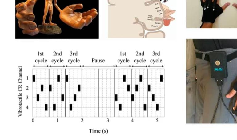

")


")