I have been promising a few people I would produce some sort of guide as to how I built my gloves. I thought it best to start a new thread, because my previous threads had become a bit cluttered. But please still refer back to those as well
I have put up a really rough and ready web-site which I believe will provide links to a set of videos to show how I made and use my gloves. Nothing fancy, so I'm not sure for example what will happen when 2 people try to view a video at the same time. I'll try to keep them short, so if you go to view one and can't, make yourself a nice cup of tea and try again.
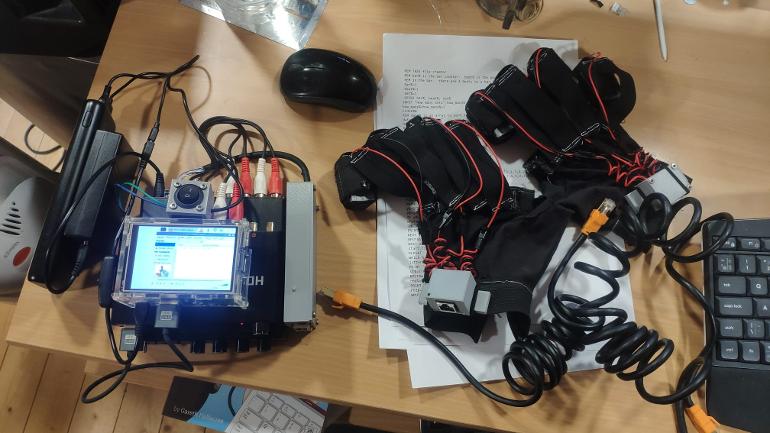
The first video - an introduction - is available now. I'll try not to take too long doing the rest. This video shows what I refer to as the Mk4 glove. A few bits change for the Mk5 - notably the tactor housing and the resistor box. But they are more similar than different
The purpose of this first video is to show what a klutsy odd method of building these gloves I have come up with - since it may well not appeal. It is very much a lego building project. Fairly simple, but hardly elegant
Anyway - the glove building project can be found here curepd2.com
Please note this is just a detailed explanation of what I have done for those who expressed interest. I make no claims regarding any use it is put to, and indeed would caution that my own experiences have not been straightforward
Written by
WinnieThePoo
To view profiles and participate in discussions please or .
OK - I've uploaded a couple more videos. I might re-do number 3 but it's alright. I also plan to add some text which explains without mumbling. I will update the parts list spreadsheet. It may take another week or so, but it should explain how they are made
Richard, who is the right professional figure to make gloves? A biomedical engineer ? I found difficulty with an electrical engineer who offered himself but with the supervision of a doctor. In fact, he argued that use by the patient can be risky without the presence of a doctor. What do you think about this? Thank you
I think there are 2 issues. Making the gloves, and supervising their use.
Anybody can make the gloves.
Ideally their use should be supervised by a medical professional (in my opinion). The problem is , of course, that none of the neurologists or mds know anything about coordinated reset. I was fortunate to have supportive medical professionals - but in the end they were not much use when I encountered problems
Making the gloves - any competent hobbyist. So far, I have demonstrated that the "brains" is a question of buying the right boxes on Amazon, and linking them up with standard cables from Amazon
Next comes the gloves - which my wife made for me, but I reckon I could have managed if I had to - maybe not as neatly
Other than that - there are some plastic parts to have 3d printed. If you ask around, you may have a friend with a 3d printer who would print them for you. But there are always professional printers. I used Xometry xometry.eu/en/3d-printing/ who can easily supply you in Italy
Then there are 3 soldering projects - resistor box, glove RJ45 box and tactor / exciter. There is no need for any electrical knowledge - although I will show in a video how to carry out some basic circuit continuity checks with a 20 euro multimeter. The soldering is a bit fiddly - but if I can do it, anyone can. Again - you may have a friend who does a bit of electronics as a hobby. Otherwise , a local electrical repairer might do it. Once you've learned the basic technique, just follow the video.
If you are going to do it yourself buy some decent wire-strippers and a proper solder station, and a "no hands" device to hold components.
On behalf of myself, Richard, Thank you SO VERY much for your EXTREMELY kind efforts in doing this for ALL of us on this forum who are SO very interested in any/all information in making the gloves. You and your team are truly appreciated for this helpful information. All of us will never know unless we try, so it is VERY much appreciated and worth the effort to at least try IMO. Thank you Again! Melodi 😁
Video 5 - the horror show. Don't worry, I won't give up my day job. I will probably try to produce some notes to go with that one. It shows how a tactor is made, but probably makes too many assumptions
A few more tweaks. The T bars are to press only on the solder tags, and not compress the exciter mechanism. I can now use shorter M3 bolts. Probably a bit rash doing the "how to build" demo on a version I hadn't built before. Also, the 9mm devices seem much less sensitive than the 13mm ones and I need maximum power. Since they are rated at 1W 4 ohms. I have ordered some 5W 10ohm resistors and will use 2 in series with 2 exciters in series. If I've done my sums right, that should be 1W per exciter and 2.6W per resistor. I tried them direct from the amp with the volume control down, and they are surprisingly good. (Am sure I must have done that long ago before I bought them, but they spooked me a bit just clipped into the existing glove). There will accordingly be a bit of a pause before the next video
Video 6 is in fact, for now 3 videos. A bit messy and rambling they nevertheless show how simple it is to build these gloves if you can use a soldering iron. That completes building the glove. There is just the resistor box to do now. The resistors arrived in the post literally 10 minutes ago, so I should have a video done by the weekend at the latest. Hopefully they make sense
first of all I can tell you that your videos will be very useful to me. A person I know is evaluating the feasibility of making Tass's gloves. He asks me for information about the intensity of the stimulus to which I don't know how to respond and which I try to address to you. The question is this: considering that a vibro-tactile device must be driven with an alternating voltage at a certain frequency, what are the amplitude limits of this voltage? What are the limits of amplitude of this current? We know from the literature only the frequency limits: 10-300Hz. Thanks for your kindness.
It's not easy to give a definitive answer. Maybe some of the engineers can give you an answer. The frequency of the signal should be 250hz - about a 3rd octave B note. The power needed to drive a device at that frequency will vary from device to device. My new exciters are driven at their maximum amplitude by 1wRMS of power (15vx0.5amps.)Now Peter Tass, using a device which vibrates perpendicular to the skin measures amplitude by measuring how much the tip of his contact point moves in and out in mm of travel. (I, and I think everyone else, interprets that as unloaded movement. That is how far the tip moves in free space - NOT - pressed against the finger tip
With my new exciter at full 1w RMS power the movement is about 0.3mm. So to get nearer to 0.1mm I will be setting the volume controls at 9 or 10 o'clock
Provided the device is operated within its design limits the precise voltage and current are not the best measure of amplitude.
The tass lra is unusual in being more like an exciter than traditional lra. Most LRAs will be buzzing too loud long before 0.1mm of perpendicular motion is achieved.
we are moving forward based on the videos and information you provide us. Is what you call an exciter actually the vibrotactile device? Is there a specific model you are referring to? Are they the same ones that Dr. Tass uses? Thank you very much Richard.
I have a parts list which needs to be updated. The exciter is the component which makes the vibrations. It is basically a loudspeaker driver without the cone. It is the device I solder a connector to in video 5. It is a Dayton DAEX-9-4SM. You will need 8 (I would buy 10 because you'll break 2). You can get them from here
You will need some items 3d printed. I can supply you with stl files. I just need to finish building these and have a bit of a tidy up - to create a full current set of 3d printing items
They are not the ones Dr Tass uses (which cost $300 each, if you can get them) - but they work on the same principle - a small diameter contact point, pre-loaded against the skin, which moves perpendicular to the skin surface, and is mounted in an enclosure which damps extraneous noise
I'm hoping to publish a parts list and outline build instructions later today. The exciter driver is a 4 channel amplifier - which will be on the parts list
Good morning Richard, could you kindly provide us with some more details on the signals generated by the driver and on the control unit that coordinates the driver's activity? Thank you very much.
The control unit is a raspberry pi 3. It's a small inexpensive Linux computer. All it does is to play a 6 channel audio file of which only 4 channels are used. It plays 100ms bursts of 0db 250 hz sine waves in one of the patterns used by stanford and Peter tass
I think if you take a look at the parts list and build description it will make more sense. I am on a 10 day break in the UK. I will try to get the last video done as soon as I get back
Hi WTP. Thank you for all of your efforts on this project, I believe it's going to help a lot of Parkies have a better life. As I mentioned in another post, I have built and been using the buzz box with some good results. I will be building your gloves next, but had a question- Would the Arduino Nano work to drive the audio amp? Also, will you make the 3d files downloadable? Thanks for all you do and congrats on the new addition to your family.
But wait, there's more! Your chosen amp is back ordered, what kind of output do we need? Parts Express has plenty of small stereo amps that might fit in the footprint of your four channel amp. If I wanted to blow my fingertips off, for $129 I could get 4x 140 watts! JK.
I appreciate a few people are waiting and I will try to get this moving next week when I get home.Most of the material I have shared has been for the mk4 glove which I am wearing as I type. But I plan to use the mk5 gloves going forward.
And the videos, the parts list and the build description refer to the mk5.
But I haven't actually built a pair yet. I am waiting for Mrs WTP to make some new smaller pod holders for me
I will share online stls of all 3d printed parts and the ac3 audio track. But I don't want to be trying to support 2 designs simultaneously. Amplifier next
That amp looks fine. As I start going through the parts list I'm finding some links are clickable and some not, even if I save another copy to edit. I'm not smart enough to figure out what's going on in xcel.
Here you go, these links are good: 1,7,8,10,13,16,17,21,23,26,41, which are all blue. All the other links are black and do not work. When I get a chance I'll try to put together a parts list for US Amazon.
I have added the links to the bottom of the Word document which describes the build. Can you take a look and let me know if any aren't working for you please?
The 9mm exciters need 1w RMS power and are not capable of handling in excess of 1w power. My resistor box achieves that for the 50w amp I am using because a friend spotted it and said "that would do". So you could just as easily use 2 stereo amps or 4 mono ampsIt's probably better to be able to control the gain on each channel independently which my 4 channel amp allows. I might get a 2nd amp and battery so I can adjust each fingertip individually instead of in pairs.
If your chosen amp has a power output which is not 50w into 8 ohms then you need to adjust the circuit. (if it is more than 50w you could just keep the volume turned down)
I'm experimenting with a 3 finger option this morning. I realised there was a connection fault on the invoice finger of the left hand and I don't have the tools with me to fix it so I have disabled and unpoppered both index fingers. It's. much nicer to use like this
Hi Winnie, I'm working on getting the parts ordered from Amazon US. One I'm not sure about is the rj45 to PCB. Does this look right: amazon.com/Network-Ethernet...
Thank you, Winnie. I will get all of my parts on the way tomorrow. I got my first batch of 3d parts, but they didn't realize there were multiples required of some of them. I'll post pics tomorrow.
Ah. Sorry. Yes I should have made it clear that you need 8 sets of the tactor housings, contact points - and a few sets (16) of the T bars - although you can cut those out of stiff carboard. I also discovered that the "winged" RJ45 housing lid prints messily. It works, but its not pretty. The wings were below the plane of the housing in the middle. I've redone it and will update the website.
Hi Winnie, just to clarify things- could you look at this picture and cross reference my letters to your descriptions or part numbers? I'm a little confused about the tactors, though that may become clear when I get the actuators Thursday. Thanks!
This illustrates the point. Bringing the pattern on the right hand to the left hand gets 1 to pinkie instead of 1 to index. Turning the pattern upside down fixes it
There are 8 wires connected to the rj45 socket on each hand. 4 pairs. Look at my right hand. The 1st pair, ch1, go naturally to my index finger. The 4th pair ch4 to my pinkie. Now across the fingers of my left hand is that same arrangement. But now the far left pair, ch1 goes to my pinkie and the far right pair, ch4 to my index finger. Back at the amplifier there are only 4 channels. We want the same signal., the same channel sent to the same finger at the same time. If I wired up the rj45 the same on both hands I would need to cross the wires over to make ch1 play on the index finger. But if I leave the wiring the same and turn the rj45 upside down, as illustrated below, now ch1 is the index again and ch4 the pinkie. So there are 2 versions of the rj45 box. The box is fixed to the glove by elastic straps over the "wings" on the box. The right hand glove has the wings on the base of the box. The left hand box has the wings on the lid. So the left hand box is fitted upside down.
OK, I more or less understand that. Can you still cross reference your 3d part numbers to the letters on my photo? I'm still not sure which part is "the box". I claim cognitive problems!
Briefly A&J house the resistors to control the power going to the exciters. It's the last video I have to do and I'll do it this weekendF is the contact point that is stuck to the exciter
"I"are t-bars used to keep the exciter in place by being dropped into the slots in D which is the middle slice of the exciter housing. E is the lid and H the base.
G is an rj45 box made from a winged box and a winged base. It needs splitting into its 2 parts and combined with B and C to make a winged base and a winged lid rj45 box
Thanks, Winnie. My actuators did arrive, but I didn't walk down to the Post Office in time and they close at noon on Saturdays. I'll pick them up Monday, but I'm still missing the Dolby box. I need to re-watch all the videos to see where that multiplug (input to the resistor box) came from.. I don't see it in my big pile'o'parts.
I think you are referring to the plug on the back of the amplifier. You can connect the wires using the screw terminals, but if you pull gently the plug will come out
I still havent built my Mk5 gloves. I havent done a full set of finger pods - partly because the DAEX -9-SM is very delicate, and I broke one of the wires on the first prototype (which, to be fair, has had quite a lot of rough handling). Investigating the best way to make them properly robust distracted me. I think a small rubber band is the solution!
But I have now tested the Mk5 resistor box. I had a fault on the Mk4 gloves (which are the ones I am using at the moment) and it was in part due to one of the RJ45s on the Mk4 box. So I plugged in and tested the Mk5. Fortunately it works beautifully. However, I had a bit of a panicky moment when I forgot that the drivers are wired in series. If one of them is not plugged in, the other one won't work. The Mk4 box is wired in parallel so you don't get that problem. Just bear in mind when testing that both hands have to be plugged in or nothing works!
Hi Winnie, my nephew noticed when printing the plunger that sticks to the actuator, that it's actually two pieces that are stuck together with support material, rather than one piece. Is that what you intended?? There is no strength at all as support material is intended to easily come apart.
Oops. Not quite sure how that happened. I have, I hope, uploaded a corrected version. I have also uploaded a corrected version of the resistor box lid with the bar for holding the RJ45's on the correct side this time. It's an easy fix without reprinting. Stick on a suitable bar with superglue. I used 2 tabs from "one-shot" eyedrops, but an ice-lolly stick, or a strip of thick cardboard would all do the job. It's just to make the support bar a bit fatter on the RJ45 side. But I have uploaded a corrected version if you prefer to print that
Content on HealthUnlocked does not replace the relationship between you and doctors or other healthcare professionals nor the advice you receive from them.
Never delay seeking advice or dialling emergency services because of something that you have read on HealthUnlocked.